HP dx7510 Service Reference Guide: HP Compaq dx7510/dx7518 Business PC - Page 66
CAUTION, Connecting the Hard Drive Cables
 |
View all HP dx7510 manuals
Add to My Manuals
Save this manual to your list of manuals |
Page 66 highlights
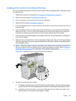
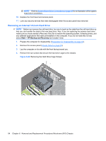
3. Connect the power cable (1) and data cable (2) to the back of the hard drive. Figure 6-30 Connecting the Hard Drive Cables CAUTION: Never crease or bend a SATA data cable tighter than a 30 mm (1.18 in) radius. A sharp bend can break the internal wires. 4. Place the hard drive cage into the chassis (1), then slide it down toward the bottom of the chassis until it locks into place (2). Figure 6-31 Installing the Hard Drive Cage 58 Chapter 6 Removal and Replacement Procedures Microtower (MT) Chassis
-
 1
1 -
2
-
3
-
4
-
5
-
6
-
7
-
8
-
9
-
10
-
11
-
12
-
13
-
14
-
15
-
16
-
17
-
18
-
19
-
20
-
21
-
22
-
23
-
24
-
25
-
26
-
27
-
28
-
29
-
30
-
31
-
32
-
33
-
34
-
35
-
36
-
37
-
38
-
39
-
40
-
41
-
42
-
43
-
44
-
45
-
46
-
47
-
48
-
49
-
50
-
51
-
52
-
53
-
54
-
55
-
56
-
57
-
58
-
59
-
60
-
 61
61 -
 62
62 -
 63
63 -
 64
64 -
 65
65 -
 66
66 -
 67
67 -
 68
68 -
 69
69 -
 70
70 -
 71
71 -
72
-
73
-
74
-
75
-
76
-
77
-
78
-
79
-
80
-
81
-
82
-
83
-
84
-
85
-
86
-
87
-
88
-
89
-
90
-
91
-
92
-
93
-
94
-
95
-
96
-
97
-
98
-
99
-
100
-
101
-
102
-
103
-
104
-
105
 |
 |
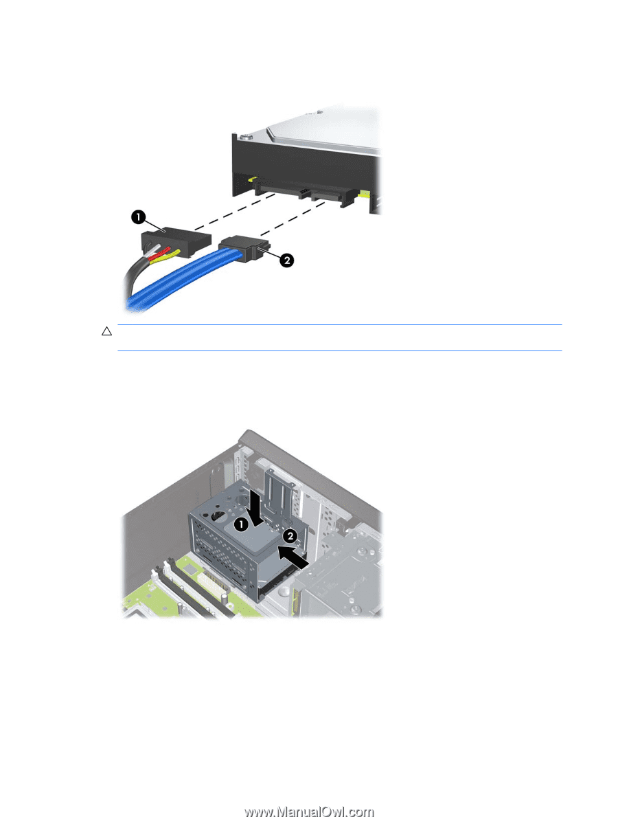
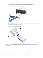
3.
Connect the power cable
(1)
and data cable
(2)
to the back of the hard drive.
Figure 6-30
Connecting the Hard Drive Cables
CAUTION:
Never crease or bend a SATA data cable tighter than a 30 mm (1.18 in) radius. A
sharp bend can break the internal wires.
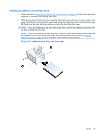
4.
Place the hard drive cage into the chassis
(1)
, then slide it down toward the bottom of the chassis
until it locks into place
(2)
.
Figure 6-31
Installing the Hard Drive Cage
58
Chapter 6
Removal and Replacement Procedures Microtower (MT) Chassis