HP dx7510 Service Reference Guide: HP Compaq dx7510/dx7518 Business PC - Page 56
System Board Drive Connections, Removal and Replacement Procedures Microtower MT Chassis
 |
View all HP dx7510 manuals
Add to My Manuals
Save this manual to your list of manuals |
Page 56 highlights
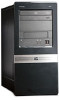
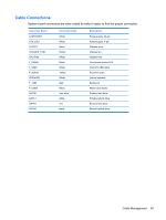
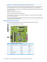
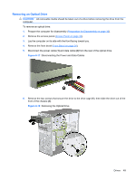
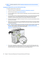
CAUTION: To prevent loss of work and damage to the computer or drive: If you are inserting or removing a drive, shut down the operating system properly, turn off the computer, and unplug the power cord. Do not remove a drive while the computer is on or in standby mode. Before handling a drive, ensure that you are discharged of static electricity. While handling a drive, avoid touching the connector. Handle a drive carefully; do not drop it. Do not use excessive force when inserting a drive. Avoid exposing a hard drive to liquids, temperature extremes, or products that have magnetic fields such as monitors or speakers. If a drive must be mailed, place the drive in a bubble-pack mailer or other protective packaging and label the package "Fragile: Handle With Care." System Board Drive Connections Refer to the following illustration and table to identify the system board drive connectors. Figure 6-16 System Board Drive Connections Table 6-3 System Board Drive Connections No. System Board Connector System Board Label 1 SATA1 SATA1 2 SATA2 SATA2 3 SATA3 SATA3 4 SATA4 SATA4 5 Media Card Reader F_USB3 6 Diskette Drive FLOPPY Color dark blue white light blue orange black black 48 Chapter 6 Removal and Replacement Procedures Microtower (MT) Chassis
-
 1
1 -
2
-
3
-
4
-
5
-
6
-
7
-
8
-
9
-
10
-
11
-
12
-
13
-
14
-
15
-
16
-
17
-
18
-
19
-
20
-
21
-
22
-
23
-
24
-
25
-
26
-
27
-
28
-
29
-
30
-
31
-
32
-
33
-
34
-
35
-
36
-
37
-
38
-
39
-
40
-
41
-
42
-
43
-
44
-
45
-
46
-
47
-
48
-
49
-
50
-
 51
51 -
 52
52 -
 53
53 -
 54
54 -
 55
55 -
 56
56 -
 57
57 -
 58
58 -
 59
59 -
 60
60 -
 61
61 -
62
-
63
-
64
-
65
-
66
-
67
-
68
-
69
-
70
-
71
-
72
-
73
-
74
-
75
-
76
-
77
-
78
-
79
-
80
-
81
-
82
-
83
-
84
-
85
-
86
-
87
-
88
-
89
-
90
-
91
-
92
-
93
-
94
-
95
-
96
-
97
-
98
-
99
-
100
-
101
-
102
-
103
-
104
-
105
 |
 |