HP dx7510 Service Reference Guide: HP Compaq dx7510/dx7518 Business PC - Page 52
Cable Management - power supply
 |
View all HP dx7510 manuals
Add to My Manuals
Save this manual to your list of manuals |
Page 52 highlights
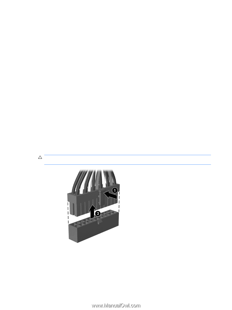
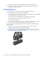
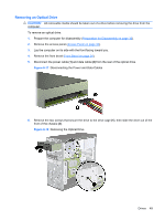
11. Lock any security devices that were disengaged when the access panel was removed. 12. Reconfigure the computer, if necessary. Refer to the Computer Setup (F10) Utility Guide for instructions on using Computer Setup. Cable Management Always follow good cable management practices when working inside the computer. ● Keep cables away from major heat sources like the heatsink. ● Do not jam cables on top of expansion cards or memory modules. Printed circuit cards like these are not designed to take excessive pressure on them. ● Some flat ribbon cables come prefolded. Never change the folds on these cables. ● Never bend a SATA data cable tighter than a 30 mm (1.18 in) radius. ● Never crease a SATA data cable. ● Do not rely on components like the drive cage, power supply, or computer cover to push cables down into the chassis. Always position the cables to lay properly by themselves. When removing the power supply power cable from the P1 connector on the system board, always follow these steps: 1. Squeeze on the top of the retaining latch attached to the cable end of the connector (1). 2. Grasp the cable end of the connector and pull it straight up (2). CAUTION: Always pull the connector - NEVER pull on the cable. Pulling on the cable could damage the cable and result in a failed power supply. 44 Chapter 6 Removal and Replacement Procedures Microtower (MT) Chassis
-
 1
1 -
2
-
3
-
4
-
5
-
6
-
7
-
8
-
9
-
10
-
11
-
12
-
13
-
14
-
15
-
16
-
17
-
18
-
19
-
20
-
21
-
22
-
23
-
24
-
25
-
26
-
27
-
28
-
29
-
30
-
31
-
32
-
33
-
34
-
35
-
36
-
37
-
38
-
39
-
40
-
41
-
42
-
43
-
44
-
45
-
46
-
 47
47 -
 48
48 -
 49
49 -
 50
50 -
 51
51 -
 52
52 -
 53
53 -
 54
54 -
 55
55 -
 56
56 -
 57
57 -
58
-
59
-
60
-
61
-
62
-
63
-
64
-
65
-
66
-
67
-
68
-
69
-
70
-
71
-
72
-
73
-
74
-
75
-
76
-
77
-
78
-
79
-
80
-
81
-
82
-
83
-
84
-
85
-
86
-
87
-
88
-
89
-
90
-
91
-
92
-
93
-
94
-
95
-
96
-
97
-
98
-
99
-
100
-
101
-
102
-
103
-
104
-
105
 |
 |