Honeywell NX4S1 User Guide - Page 62
Configuring Other I/O & Groups Tab, 2.7.1 Inputs Tab
 |
View all Honeywell NX4S1 manuals
Add to My Manuals
Save this manual to your list of manuals |
Page 62 highlights
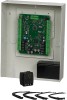
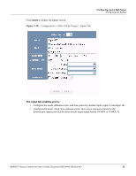
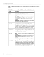
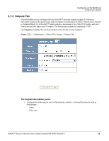
Configuring via the Web Server Configuring the System Table 2-9: Cards > Reports Field Descriptions (continued) Field Description Activation Date Shows the date the card was activated. Expiration Date Shows the date the card expires. Use Limit Indicates the number of times the card will be granted access. APB State Indicates whether or not anti-passback is enabled on the card. Note 1 Displays informational text that may have been entered in the Note 1 field. Note 2 Displays informational text that may have been entered in the Note 2 field. 2.7 Configuring Other I/O & Groups Tab The NetAXS™ panel provides up to 14 inputs and eight outputs. Two of the inputs and four of the outputs are "other" inputs and outputs, because you can use them for other than door lock/unlock functions. This section explains how to configure these other inputs, outputs, and groups (for pulse and time zone). 2.7.1 Inputs Tab This tab enables you to configure other input devices on inputs 13 and 14 on Terminal Block 8, and on the inputs on downstream NX4IN boards daisy-chained to Terminal Block 10. The downstream inputs are numbered 25-96. Note: The NetAXS™ panel supports two downstream board types: • NX4IN - Provides 32 inputs and no outputs. • NX4OUT - Provides two inputs and 16 outputs. A NetAXS™ panel supports a maximum of six daisy-chained downstream boards-two NX4IN boards and four NX4OUT. An NX4IN module has 32 supervised, four-state inputs that are limited to 2.2K ohms resistance. The NX4OUT has two supervised inputs and 16 SPDT relay outputs; each input is limited to 2.2K ohms resistance. Each board is configured with a unique address in the Configuration > System > Downstream Devices tab (see "Downstream Devices Tab" on page 23). On panels with internal power supply, the Power Fail input generates an alarm when primary power is lost as indicated by the power supply. The Panel Tamper input generates an alarm when the NetAXS™ cabinet has been forced open. The Downstream inputs are available for general use. Note: You can also configure the Power Fail and the Panel Tamper inputs for general use, if you choose not to wire them for power and tamper detection. 52 www.honeywell.com
-
 1
1 -
2
-
3
-
4
-
5
-
6
-
7
-
8
-
9
-
10
-
11
-
12
-
13
-
14
-
15
-
16
-
17
-
18
-
19
-
20
-
21
-
22
-
23
-
24
-
25
-
26
-
27
-
28
-
29
-
30
-
31
-
32
-
33
-
34
-
35
-
36
-
37
-
38
-
39
-
40
-
41
-
42
-
43
-
44
-
45
-
46
-
47
-
48
-
49
-
50
-
51
-
52
-
53
-
54
-
55
-
56
-
 57
57 -
 58
58 -
 59
59 -
 60
60 -
 61
61 -
 62
62 -
 63
63 -
 64
64 -
 65
65 -
 66
66 -
 67
67 -
68
-
69
-
70
-
71
-
72
-
73
-
74
-
75
-
76
-
77
-
78
-
79
-
80
-
81
-
82
-
83
-
84
-
85
-
86
-
87
-
88
-
89
-
90
-
91
-
92
-
93
-
94
-
95
-
96
-
97
-
98
-
99
-
100
-
101
-
102
-
103
-
104
-
105
-
106
-
107
-
108
-
109
 |
 |