Honeywell NX4S1 User Guide - Page 70
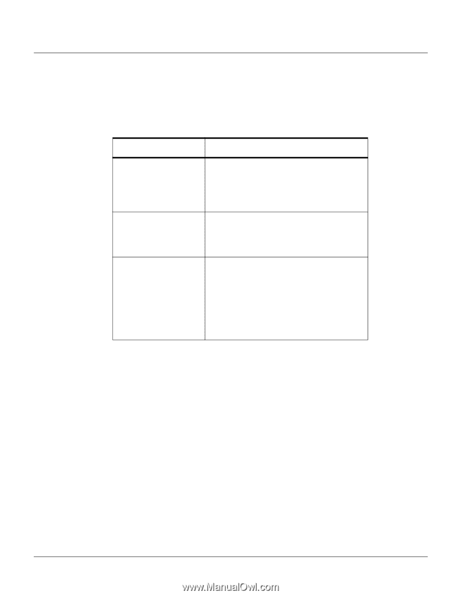
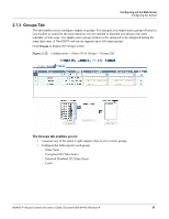
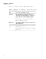
Table 2-13, Configuration > Interlocks > Field Descriptions
 |
View all Honeywell NX4S1 manuals
Add to My Manuals
Save this manual to your list of manuals |
Page 70 highlights
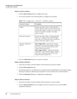
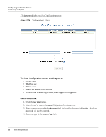
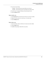
Configuring via the Web Server Configuring the System Steps to create an interlock: 1. Click the New Interlock button to display the screen. 2. Use the descriptions in the following table to configure the interlock: Table 2-13: Configuration > Interlocks > Field Descriptions Interlock element Description Trigger Specifies the input, output, or output group for which a change of state will cause a reaction from another input, output, or group. Also, use the drop down list to specify the number of the input, output, or group. Reacting Component Specifies the input, output, or output group that will react to a change of state from the trigger point. Also, use the drop down list to specify the number of the input, output, or group. Reacting Component's Action Upon Trigger Alarm - Specifies the reacting component's action when the trigger's change of state occurs. Select the action from the Upon Trigger Alarm drop down list. Upon Trigger Normal - Specifies the reacting component's action when the trigger's change of state occurs. Select the action from the Upon Trigger Normal drop down list. 3. Click the Add Interlock button to create the interlock. Steps to modify an interlock: 1. In the Int Lk column, click the number of the interlock you want to modify. 2. Click the New Interlock button. 3. Use the descriptions in the table above to make the desired modifications in the empty Trigger, Reacting Component, and Reacting Component's Action fields for the selected interlock. 4. Click the Add Interlock button to complete the modification. Steps to delete an interlock: 1. In the Int Lk column, click the number of the interlock you want to delete. 2. Click the Delete Interlock button to display the Delete Interlock screen, and click OK to complete the deletion. 60 www.honeywell.com
-
 1
1 -
2
-
3
-
4
-
5
-
6
-
7
-
8
-
9
-
10
-
11
-
12
-
13
-
14
-
15
-
16
-
17
-
18
-
19
-
20
-
21
-
22
-
23
-
24
-
25
-
26
-
27
-
28
-
29
-
30
-
31
-
32
-
33
-
34
-
35
-
36
-
37
-
38
-
39
-
40
-
41
-
42
-
43
-
44
-
45
-
46
-
47
-
48
-
49
-
50
-
51
-
52
-
53
-
54
-
55
-
56
-
57
-
58
-
59
-
60
-
61
-
62
-
63
-
64
-
 65
65 -
 66
66 -
 67
67 -
 68
68 -
 69
69 -
 70
70 -
 71
71 -
 72
72 -
 73
73 -
 74
74 -
 75
75 -
76
-
77
-
78
-
79
-
80
-
81
-
82
-
83
-
84
-
85
-
86
-
87
-
88
-
89
-
90
-
91
-
92
-
93
-
94
-
95
-
96
-
97
-
98
-
99
-
100
-
101
-
102
-
103
-
104
-
105
-
106
-
107
-
108
-
109
 |
 |