IBM 25R0012 User Guide - Page 56
Attention
 |
UPC - 000435800176
View all IBM 25R0012 manuals
Add to My Manuals
Save this manual to your list of manuals |
Page 56 highlights
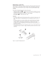
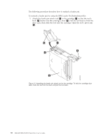
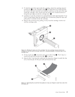
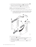
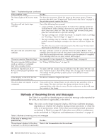
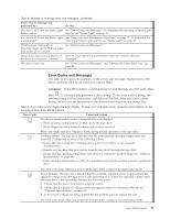
7. Position the tape in the alignment groove of the leader pin attach tool 1 . 8. Place a new C-clip into the retention groove 2 () on the leader pin attachment tool and make sure that the clip's open side faces up. 9. Place the leader pin into the cavity 3 of the leader pin attach tool. Attention: To prevent the leader pin from rolling into the cartridge, in the following step use care when folding the tape over the pin. 10. Fold the tape over the leader pin and hold it with your fingers (see Figure 18). Note: Use care to ensure that the tape is centered over the leader pin. Failure to properly center the tape on the pin will cause the repaired cartridge to fail. When the tape is properly centered, a 0.25-mm (0.01-in.) gap exists on both sides of the pin. 2 1 4 3 A67E0037 6 5 Figure 18. Attaching the leader pin to the tape 11. Close the pivot arm 4 of the leader pin attach tool by swinging it over the leader pin so that the C-clip snaps onto the pin and the tape. 12. Swing the pivot arm open and trim the excess tape 5 so that it is flush with the reattached leader pin 6 . 13. Use your fingers to remove the leader pin from the cavity 3 in the leader pin attach tool. 40 IBM 400/800GB LTO3 Tape Drive User's Guide
-
 1
1 -
2
-
3
-
4
-
5
-
6
-
7
-
8
-
9
-
10
-
11
-
12
-
13
-
14
-
15
-
16
-
17
-
18
-
19
-
20
-
21
-
22
-
23
-
24
-
25
-
26
-
27
-
28
-
29
-
30
-
31
-
32
-
33
-
34
-
35
-
36
-
37
-
38
-
39
-
40
-
41
-
42
-
43
-
44
-
45
-
46
-
47
-
48
-
49
-
50
-
 51
51 -
 52
52 -
 53
53 -
 54
54 -
 55
55 -
 56
56 -
 57
57 -
 58
58 -
 59
59 -
 60
60 -
 61
61 -
62
-
63
-
64
-
65
-
66
-
67
-
68
-
69
-
70
-
71
-
72
-
73
-
74
-
75
-
76
-
77
-
78
-
79
-
80
-
81
-
82
-
83
-
84
-
85
-
86
-
87
-
88
-
89
-
90
-
91
-
92
-
93
-
94
-
95
-
96
-
97
-
98
-
99
-
100
-
101
-
102
-
103
-
104
-
105
-
106
-
107
-
108
-
109
-
110
-
111
-
112
-
113
-
114
-
115
-
116
-
117
-
118
-
119
-
120
 |
 |
