IBM 25R0012 User Guide - Page 76
mechanism.
 |
UPC - 000435800176
View all IBM 25R0012 manuals
Add to My Manuals
Save this manual to your list of manuals |
Page 76 highlights
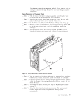
This rotates the threader motor worm gear 4 clockwise, drawing the LBA into the cartridge. 2 8 1 3 7 6 5 9 4 a82ru009 Figure 25. Drive with cover removed to reveal gear train. 1 Loader motor worm gear 6 Threader mechanism gear 2 Cartridge loader tray guide bearing 7 Lever 3 Rotator stub 8 Loader mechanism gear 4 Threader motor worm gear 9 Threader worm gear 5 Threader intermediate gear __ Step 7. As the tape leader block assembly (LBA) is secured in the cartridge, you should hear the LBA retention spring clips click into place. If you do not hear the click, continue rolling until the threader motor worm gear 4 stops. The LBA is in the correct position. Note: Be sure to keep tension on the tape as the LBA is drawn into the cartridge by using a hex wrench. __ Step 8. Notice the: a. Loader mechanism gear 6 nearest the front of the drive that actuates the cartridge loader mechanism. b. Position of the rotate stub 3 . c. Front loader motor worm gear 1 . Rotating this gear allows the loader mechanism gear 8 to turn. 60 IBM 400/800GB LTO3 Tape Drive User's Guide
-
 1
1 -
2
-
3
-
4
-
5
-
6
-
7
-
8
-
9
-
10
-
11
-
12
-
13
-
14
-
15
-
16
-
17
-
18
-
19
-
20
-
21
-
22
-
23
-
24
-
25
-
26
-
27
-
28
-
29
-
30
-
31
-
32
-
33
-
34
-
35
-
36
-
37
-
38
-
39
-
40
-
41
-
42
-
43
-
44
-
45
-
46
-
47
-
48
-
49
-
50
-
51
-
52
-
53
-
54
-
55
-
56
-
57
-
58
-
59
-
60
-
61
-
62
-
63
-
64
-
65
-
66
-
67
-
68
-
69
-
70
-
 71
71 -
 72
72 -
 73
73 -
 74
74 -
 75
75 -
 76
76 -
 77
77 -
 78
78 -
 79
79 -
 80
80 -
 81
81 -
82
-
83
-
84
-
85
-
86
-
87
-
88
-
89
-
90
-
91
-
92
-
93
-
94
-
95
-
96
-
97
-
98
-
99
-
100
-
101
-
102
-
103
-
104
-
105
-
106
-
107
-
108
-
109
-
110
-
111
-
112
-
113
-
114
-
115
-
116
-
117
-
118
-
119
-
120
 |
 |
