IBM 72336RU User Manual - Page 23
Server controls, connectors, LEDs, and power, Front view, Hard disk drive activity LED
 |
View all IBM 72336RU manuals
Add to My Manuals
Save this manual to your list of manuals |
Page 23 highlights
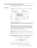
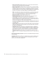
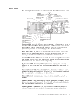
Server controls, connectors, LEDs, and power This section describes the controls, connectors, and light-emitting diodes (LEDs) and how to turn the server on and off. Front view The following illustration shows the controls, LEDs, and connectors on the front of the server. Hard disk drive activity LED Hard disk drive status LED USB connectors DVD-eject button DVD drive activity LED Operator information panel 1 2 3 4 Scalability LED Electrostatic-discharge connector Hard disk drive activity LED: On some server models, each hot-swap hard disk drive has an activity LED. When this LED is flashing, it indicates that the drive is in use. Hard disk drive status LED: On some server models, each hot-swap hard disk drive has a status LED. When this LED is lit continuously, that individual drive is faulty. When the drive is connected to the integrated SAS controller with RAID capabilities, a flashing status LED indicates that the drive is a secondary drive in a mirrored pair and the drive is being synchronized. USB connectors: Connect USB devices to these connectors. DVD-eject button: Press this button to release a CD or DVD from the DVD drive. DVD drive activity LED: When this LED is lit, it indicates that the DVD drive is in use. Operator information panel: This panel contains controls and LEDs. The following illustration shows the controls and LEDs on the operator information panel. Power-control button/power-on LED Ethernet icon LED Information LED System-error LED 1 2 Power-control button cover Ethernet port activity LEDs Locator button/locator LED The following controls and LEDs are on the operator information panel: Chapter 1. The System x3850 M2 and System x3950 M2 server 11
-
 1
1 -
2
-
3
-
4
-
5
-
6
-
7
-
8
-
9
-
10
-
11
-
12
-
13
-
14
-
15
-
16
-
17
-
 18
18 -
 19
19 -
 20
20 -
 21
21 -
 22
22 -
 23
23 -
 24
24 -
 25
25 -
 26
26 -
 27
27 -
 28
28 -
29
-
30
-
31
-
32
-
33
-
34
-
35
-
36
-
37
-
38
-
39
-
40
-
41
-
42
-
43
-
44
-
45
-
46
-
47
-
48
-
49
-
50
-
51
-
52
-
53
-
54
-
55
-
56
-
57
-
58
-
59
-
60
-
61
-
62
-
63
-
64
-
65
-
66
-
67
-
68
-
69
-
70
-
71
-
72
-
73
-
74
-
75
-
76
-
77
-
78
-
79
-
80
-
81
-
82
-
83
-
84
-
85
-
86
-
87
-
88
-
89
-
90
-
91
-
92
-
93
-
94
-
95
-
96
-
97
-
98
-
99
-
100
-
101
-
102
 |
 |
