IBM 72336RU User Manual - Page 67
Completing the installation, I/O board.
 |
View all IBM 72336RU manuals
Add to My Manuals
Save this manual to your list of manuals |
Page 67 highlights
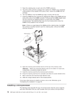
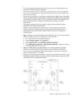
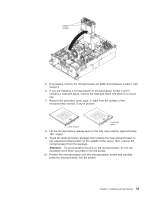
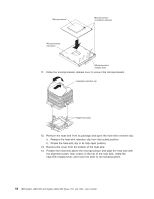
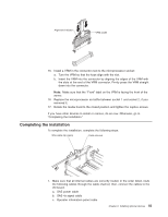
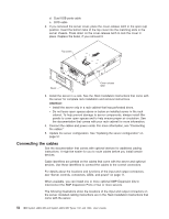
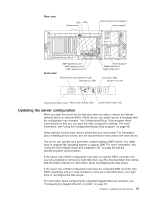
Alignment indicator VRM cradle 15. Install a VRM in the connector next to the microprocessor socket: a. Turn the VRM so that the keys align with the slot. b. Insert the VRM into the connector by aligning the edges of the VRM with the slots at the end of the VRM connector. Firmly press the VRM straight down into the connector. Note: Make sure that the "Front" label on the VRM is facing the front of the server. 16. Replace the microprocessor air baffle between socket 1 and socket 2, if you removed it. 17. Rotate the media hood to the closed position and tighten the captive screws. If you have other devices to install or remove, do so now. Otherwise, go to "Completing the installation." Completing the installation To complete the installation, complete the following steps. Wire cable clip (open) Cable channel 1. Make sure that all internal cables are correctly routed. In the order listed, route the following cables through the cable channel; then, connect the cables to the I/O board. a. SAS power cable b. SAS 4x signal cable c. Operator information panel cable Chapter 2. Installing optional devices 55
-
 1
1 -
2
-
3
-
4
-
5
-
6
-
7
-
8
-
9
-
10
-
11
-
12
-
13
-
14
-
15
-
16
-
17
-
18
-
19
-
20
-
21
-
22
-
23
-
24
-
25
-
26
-
27
-
28
-
29
-
30
-
31
-
32
-
33
-
34
-
35
-
36
-
37
-
38
-
39
-
40
-
41
-
42
-
43
-
44
-
45
-
46
-
47
-
48
-
49
-
50
-
51
-
52
-
53
-
54
-
55
-
56
-
57
-
58
-
59
-
60
-
61
-
 62
62 -
 63
63 -
 64
64 -
 65
65 -
 66
66 -
 67
67 -
 68
68 -
 69
69 -
 70
70 -
 71
71 -
 72
72 -
73
-
74
-
75
-
76
-
77
-
78
-
79
-
80
-
81
-
82
-
83
-
84
-
85
-
86
-
87
-
88
-
89
-
90
-
91
-
92
-
93
-
94
-
95
-
96
-
97
-
98
-
99
-
100
-
101
-
102
 |
 |
