IBM 72336RU User Manual - Page 68
Connecting the cables, Rack Installation Instructions
 |
View all IBM 72336RU manuals
Add to My Manuals
Save this manual to your list of manuals |
Page 68 highlights
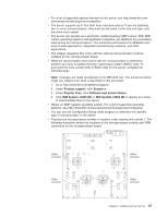
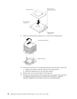
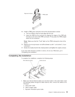
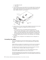
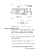
d. Dual USB ports cable e. DVD cable 2. If you removed the server cover, place the cover-release latch in the open (up) position. Insert the bottom tabs of the top cover into the matching slots in the server chassis. Press down on the cover-release latch to lock the cover in place. Replace the bezel, if you removed it. Top cover Bezel Cover release latch 3. Install the server in a rack. See the Rack Installation Instructions that come with the server for complete rack installation and removal instructions. Attention: v Install the server only in a rack cabinet that has perforated doors. v Do not leave open spaces above or below an installed server in the rack cabinet. To help prevent damage to server components, always install filler panels to cover open spaces and to help ensure proper air circulation. See the documentation that comes with your rack cabinet for more information. 4. Connect the cables and power cords. For more information, see "Connecting the cables." 5. Update the server configuration. See "Updating the server configuration" on page 57. Connecting the cables See the documentation that comes with optional devices for additional cabling instructions. It might be easier for you to route cables before you install certain devices. Cable identifiers are printed on the cables that come with the server and optional devices. Use these identifiers to connect the cables to the correct connectors. For details about the locations and functions of the input and output connectors, see "Server controls, connectors, LEDs, and power" on page 11. When available, you can install one or more optional SMP Expansion kits to interconnect the SMP Expansion Ports of two or more servers. The following illustrations show the locations of the input and output connectors on the server. Detailed cabling instructions are in the Rack Installation Instructions that come with the server. 56 IBM System x3850 M2 and System x3950 M2 Types 7141 and 7233: User's Guide
-
 1
1 -
2
-
3
-
4
-
5
-
6
-
7
-
8
-
9
-
10
-
11
-
12
-
13
-
14
-
15
-
16
-
17
-
18
-
19
-
20
-
21
-
22
-
23
-
24
-
25
-
26
-
27
-
28
-
29
-
30
-
31
-
32
-
33
-
34
-
35
-
36
-
37
-
38
-
39
-
40
-
41
-
42
-
43
-
44
-
45
-
46
-
47
-
48
-
49
-
50
-
51
-
52
-
53
-
54
-
55
-
56
-
57
-
58
-
59
-
60
-
61
-
62
-
 63
63 -
 64
64 -
 65
65 -
 66
66 -
 67
67 -
 68
68 -
 69
69 -
 70
70 -
 71
71 -
 72
72 -
 73
73 -
74
-
75
-
76
-
77
-
78
-
79
-
80
-
81
-
82
-
83
-
84
-
85
-
86
-
87
-
88
-
89
-
90
-
91
-
92
-
93
-
94
-
95
-
96
-
97
-
98
-
99
-
100
-
101
-
102
 |
 |
