IBM 72336RU User Manual - Page 52
Disabled, Memory Settings, DIMM pair installation, order, Memory card, Connector numbers
 |
View all IBM 72336RU manuals
Add to My Manuals
Save this manual to your list of manuals |
Page 52 highlights
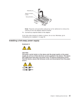
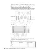
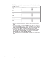
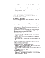
designated as Disabled in the Memory Settings menu. In this case, you must re-enable the row in the Configuration/Setup Utility program or reload the default memory settings. v When you restart the server after you add or remove a DIMM, the server displays a message that the memory configuration has changed. v Populate the memory-card connectors in numeric order, starting with connector 1. The following illustration shows the locations of the memory-card connectors. Memory card 1 12 Memory card 2 Memory card 4 3 4 Memory card 3 v The following illustration shows the DIMM connectors on the memory card. DIMM 1 DIMM 2 DIMM 3 DIMM 4 DIMM 5 DIMM 6 DIMM 7 DIMM 8 v Install the DIMMs on each memory card in the order shown in the following tables, depending on which memory configuration you want to use. You must install at least one pair of DIMMs on each memory card. Table 5. Low-cost memory-card installation sequence DIMM pair installation order Memory card Connector numbers First 1 Second 2 1 and 5 1 and 5 Third 1 2 and 6 Fourth 2 2 and 6 40 IBM System x3850 M2 and System x3950 M2 Types 7141 and 7233: User's Guide
-
 1
1 -
2
-
3
-
4
-
5
-
6
-
7
-
8
-
9
-
10
-
11
-
12
-
13
-
14
-
15
-
16
-
17
-
18
-
19
-
20
-
21
-
22
-
23
-
24
-
25
-
26
-
27
-
28
-
29
-
30
-
31
-
32
-
33
-
34
-
35
-
36
-
37
-
38
-
39
-
40
-
41
-
42
-
43
-
44
-
45
-
46
-
 47
47 -
 48
48 -
 49
49 -
 50
50 -
 51
51 -
 52
52 -
 53
53 -
 54
54 -
 55
55 -
 56
56 -
 57
57 -
58
-
59
-
60
-
61
-
62
-
63
-
64
-
65
-
66
-
67
-
68
-
69
-
70
-
71
-
72
-
73
-
74
-
75
-
76
-
77
-
78
-
79
-
80
-
81
-
82
-
83
-
84
-
85
-
86
-
87
-
88
-
89
-
90
-
91
-
92
-
93
-
94
-
95
-
96
-
97
-
98
-
99
-
100
-
101
-
102
 |
 |
