IBM 72336RU User Manual - Page 57
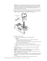
Hot-replacing a memory card, unpainted surface on the outside of the server; then, remove the memory
 |
View all IBM 72336RU manuals
Add to My Manuals
Save this manual to your list of manuals |
Page 57 highlights
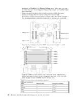
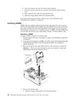
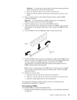
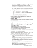
c. Install DIMMs in the memory card (see "Installing DIMMs" on page 46). 5. Add the memory card. Attention: When you move the memory card, do not allow it to touch any components or structures inside the server. a. Grasp the memory card by the retention levers and turn the memory card so that the connector aligns with the connector on the microprocessor board and the guides on the chassis. b. Insert the memory card into the memory-card connector. c. Press the memory card into the connector and close the retention levers. d. Slide the orange release latch to the locked position. If you have other devices to install or remove, do so now. Otherwise, go to "Completing the installation" on page 55. Hot-replacing a memory card For you to hot-replace a memory card, memory mirroring must be enabled. See "Active Memory" on page 43 for information about how to enable memory mirroring. To hot-replace a memory card in the server, complete the following steps: 1. Read the safety information that begins on page v and "Installation guidelines" on page 28. Attention: Static electricity that is released to internal server components when the server is powered-on might cause the server to halt, which might result in the loss of data. To avoid this potential problem, always use an electrostatic-discharge wrist strap or other grounding system when you work inside the server with the power on. 2. Remove the server cover (see "Removing the cover and bezel" on page 30). 3. Make sure the memory hot-swap enabled LED is lit. If the LED is not lit, enable memory mirroring (see "Active Memory" on page 43). 4. Prepare the new memory card: a. Touch the static-protective package that contains the memory card to any unpainted surface on the outside of the server; then, remove the memory card from the package. b. Place the memory card on a flat, static-protective surface, with the DIMM connectors facing up. c. Install memory DIMMs in the memory card (see "Installing DIMMs" on page 46). Attention: When you move the memory card, do not allow it to touch any components or structures inside the server. 5. Remove the memory card from the server: a. Slide the orange release latch to the unlocked position. Attention: To avoid loss of data, make sure that the memory port power LED is off before you remove the memory card. b. Make sure that the retention levers on the edge of the memory card are fully open. c. Lift the memory card out of the server. 6. Replace the memory card: a. Grasp the new memory card by the retention levers and turn the memory card so that the connector aligns with the connector on the microprocessor board and the guides on the chassis. Chapter 2. Installing optional devices 45
-
 1
1 -
2
-
3
-
4
-
5
-
6
-
7
-
8
-
9
-
10
-
11
-
12
-
13
-
14
-
15
-
16
-
17
-
18
-
19
-
20
-
21
-
22
-
23
-
24
-
25
-
26
-
27
-
28
-
29
-
30
-
31
-
32
-
33
-
34
-
35
-
36
-
37
-
38
-
39
-
40
-
41
-
42
-
43
-
44
-
45
-
46
-
47
-
48
-
49
-
50
-
51
-
 52
52 -
 53
53 -
 54
54 -
 55
55 -
 56
56 -
 57
57 -
 58
58 -
 59
59 -
 60
60 -
 61
61 -
 62
62 -
63
-
64
-
65
-
66
-
67
-
68
-
69
-
70
-
71
-
72
-
73
-
74
-
75
-
76
-
77
-
78
-
79
-
80
-
81
-
82
-
83
-
84
-
85
-
86
-
87
-
88
-
89
-
90
-
91
-
92
-
93
-
94
-
95
-
96
-
97
-
98
-
99
-
100
-
101
-
102
 |
 |