IBM 72336RU User Manual - Page 35
Microprocessor-board LEDs, Description
 |
View all IBM 72336RU manuals
Add to My Manuals
Save this manual to your list of manuals |
Page 35 highlights
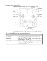
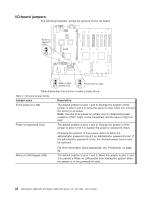
Microprocessor-board LEDs The following illustration shows the LEDs on the microprocessor board. Board fault LED FPGA heartbeat LED BMC heartbeat LED Microprocessor 3 error LED VRM 3 error LED 3 Microprocessor 4 error LED 4 VRM 4 error LED Microprocessor 1 error LED VRM 1 error LED 1 2 Microprocessor 2 error LED VRM 2 error LED Machine check LED Power good LED Scalability enabled LED Table 2 describes the function of each status LED other than light path diagnostics LEDs. Table 2. Microprocessor-board status LEDs (other than light path diagnostics) LED Description BMC heartbeat When this LED is flashing, it indicates normal operation of the baseboard management controller. FPGA heartbeat When this LED is flashing, it indicates normal operation of the FPGA (field-programmable gate array) chip. Machine check When this LED is lit continuously, the server is prepared to capture a machine check. When this LED is flashing, the server has captured a machine check. When this LED is off, the server is not prepared to capture a machine check. Chapter 2. Installing optional devices 23
-
 1
1 -
2
-
3
-
4
-
5
-
6
-
7
-
8
-
9
-
10
-
11
-
12
-
13
-
14
-
15
-
16
-
17
-
18
-
19
-
20
-
21
-
22
-
23
-
24
-
25
-
26
-
27
-
28
-
29
-
 30
30 -
 31
31 -
 32
32 -
 33
33 -
 34
34 -
 35
35 -
 36
36 -
 37
37 -
 38
38 -
 39
39 -
 40
40 -
41
-
42
-
43
-
44
-
45
-
46
-
47
-
48
-
49
-
50
-
51
-
52
-
53
-
54
-
55
-
56
-
57
-
58
-
59
-
60
-
61
-
62
-
63
-
64
-
65
-
66
-
67
-
68
-
69
-
70
-
71
-
72
-
73
-
74
-
75
-
76
-
77
-
78
-
79
-
80
-
81
-
82
-
83
-
84
-
85
-
86
-
87
-
88
-
89
-
90
-
91
-
92
-
93
-
94
-
95
-
96
-
97
-
98
-
99
-
100
-
101
-
102
 |
 |
