IBM 72336RU User Manual - Page 37
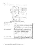
I/O-board connectors, I/O-board LEDs, The following illustration shows the LEDs on the I/O board.
 |
View all IBM 72336RU manuals
Add to My Manuals
Save this manual to your list of manuals |
Page 37 highlights
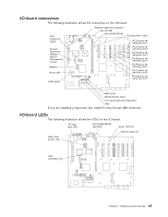
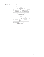
I/O-board connectors The following illustration shows the connectors on the I/O board. SAS backplane signal Remote Supervisor Adapter II System Management access Battery Front USB SATA signal Remote Supervisor Adapter II Internal USB ServeRAID-MR10k Hot-plug switch card PCI Express x8 (x8 lanes) slot 1 PCI Express x8 (x8 lanes) slot 2 PCI Express x8 (x8 lanes) slot 3 PCI Express x8 (x8 lanes) slot 4 PCI Express x8 (x8 lanes) slot 5 PCI Express x8 (x8 lanes) slot 6 PCI Express x8 (x8 lanes) slot 7 SATA power SAS backplane power Front panel/light path diagnostics DVD If you are installing a hypervisor key, install it in the internal USB connector. I/O-board LEDs The following illustration shows the LEDs on the I/O board. I/O card fault LED ServeRAID-MR10k fault LED Power LED (2x) Attention LED (7x) RAID write protect LED SAS heartbeat LED Chapter 2. Installing optional devices 25
-
 1
1 -
2
-
3
-
4
-
5
-
6
-
7
-
8
-
9
-
10
-
11
-
12
-
13
-
14
-
15
-
16
-
17
-
18
-
19
-
20
-
21
-
22
-
23
-
24
-
25
-
26
-
27
-
28
-
29
-
30
-
31
-
 32
32 -
 33
33 -
 34
34 -
 35
35 -
 36
36 -
 37
37 -
 38
38 -
 39
39 -
 40
40 -
 41
41 -
 42
42 -
43
-
44
-
45
-
46
-
47
-
48
-
49
-
50
-
51
-
52
-
53
-
54
-
55
-
56
-
57
-
58
-
59
-
60
-
61
-
62
-
63
-
64
-
65
-
66
-
67
-
68
-
69
-
70
-
71
-
72
-
73
-
74
-
75
-
76
-
77
-
78
-
79
-
80
-
81
-
82
-
83
-
84
-
85
-
86
-
87
-
88
-
89
-
90
-
91
-
92
-
93
-
94
-
95
-
96
-
97
-
98
-
99
-
100
-
101
-
102
 |
 |
