IBM 72336RU User Manual - Page 65
excessive force when you press it into the socket.
 |
View all IBM 72336RU manuals
Add to My Manuals
Save this manual to your list of manuals |
Page 65 highlights
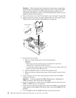
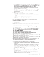
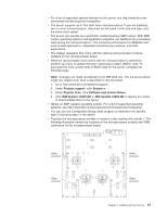
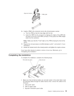
Captive screws 5. If necessary, remove the microprocessor air baffle from between socket 1 and socket 2. 6. If you are installing a microprocessor in microprocessor socket 2 and it contains a heat-sink blank, remove the heat-sink blank and store it for future use. 7. Remove the protective cover, tape, or label from the surface of the microprocessor socket, if any is present. Lever closed Lever fully open 8. Lift the microprocessor-release lever to the fully open position (approximately 135° angle). 9. Touch the static-protective package that contains the new microprocessor to any unpainted metal surface on the outside of the server; then, remove the microprocessor from the package. Attention: To avoid bending the pins on the microprocessor, do not use excessive force when you press it into the socket. 10. Position the microprocessor over the microprocessor socket and carefully press the microprocessor into the socket. Chapter 2. Installing optional devices 53
-
 1
1 -
2
-
3
-
4
-
5
-
6
-
7
-
8
-
9
-
10
-
11
-
12
-
13
-
14
-
15
-
16
-
17
-
18
-
19
-
20
-
21
-
22
-
23
-
24
-
25
-
26
-
27
-
28
-
29
-
30
-
31
-
32
-
33
-
34
-
35
-
36
-
37
-
38
-
39
-
40
-
41
-
42
-
43
-
44
-
45
-
46
-
47
-
48
-
49
-
50
-
51
-
52
-
53
-
54
-
55
-
56
-
57
-
58
-
59
-
 60
60 -
 61
61 -
 62
62 -
 63
63 -
 64
64 -
 65
65 -
 66
66 -
 67
67 -
 68
68 -
 69
69 -
 70
70 -
71
-
72
-
73
-
74
-
75
-
76
-
77
-
78
-
79
-
80
-
81
-
82
-
83
-
84
-
85
-
86
-
87
-
88
-
89
-
90
-
91
-
92
-
93
-
94
-
95
-
96
-
97
-
98
-
99
-
100
-
101
-
102
 |
 |
