IBM 72336RU User Manual - Page 54
system-error LED on the front of the server, indicating that there is a problem
 |
View all IBM 72336RU manuals
Add to My Manuals
Save this manual to your list of manuals |
Page 54 highlights
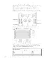
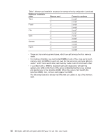
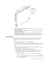
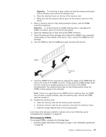
Table 7. Memory-card installation sequence for memory-mirroring configuration (continued) DIMM pair installation order Memory card Connector numbers Third 1 2 and 6 2 2 and 6 Fourth 3 2 and 6 4 2 and 6 Fifth 1 3 and 7 2 3 and 7 Sixth 3 3 and 7 4 3 and 7 Seventh 1 4 and 8 2 4 and 8 Eighth 3 4 and 8 4 4 and 8 v There are four memory power buses, which are split among the four memory cards. v For memory mirroring, you must install DIMMs in sets of four, one pair in each memory card. All DIMMs in each set must be the same size and type. Memory cards 1 and 2 mirror each other, and memory cards 3 and 4 mirror each other. v If a problem with a DIMM is detected, light path diagnostics will light the system-error LED on the front of the server, indicating that there is a problem and guiding you to the defective DIMM. When this occurs, first identify the defective DIMM; then, remove and replace the DIMM. The following illustration shows the LEDs that are visible on top of the memory card. 42 IBM System x3850 M2 and System x3950 M2 Types 7141 and 7233: User's Guide
-
 1
1 -
2
-
3
-
4
-
5
-
6
-
7
-
8
-
9
-
10
-
11
-
12
-
13
-
14
-
15
-
16
-
17
-
18
-
19
-
20
-
21
-
22
-
23
-
24
-
25
-
26
-
27
-
28
-
29
-
30
-
31
-
32
-
33
-
34
-
35
-
36
-
37
-
38
-
39
-
40
-
41
-
42
-
43
-
44
-
45
-
46
-
47
-
48
-
 49
49 -
 50
50 -
 51
51 -
 52
52 -
 53
53 -
 54
54 -
 55
55 -
 56
56 -
 57
57 -
 58
58 -
 59
59 -
60
-
61
-
62
-
63
-
64
-
65
-
66
-
67
-
68
-
69
-
70
-
71
-
72
-
73
-
74
-
75
-
76
-
77
-
78
-
79
-
80
-
81
-
82
-
83
-
84
-
85
-
86
-
87
-
88
-
89
-
90
-
91
-
92
-
93
-
94
-
95
-
96
-
97
-
98
-
99
-
100
-
101
-
102
 |
 |
