IBM 72336RU User Manual - Page 46
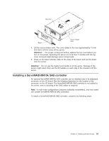
into the adapter connector., Optionally, if you are installing the adapter in slot 1 through slot 5
 |
View all IBM 72336RU manuals
Add to My Manuals
Save this manual to your list of manuals |
Page 46 highlights
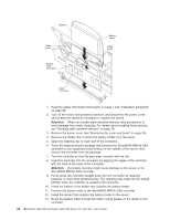
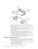
Attention Tab LED (yellow) Power LED (green) Adapter retention latch PCI divider Note: The adapter-retention bracket is not shown in the illustration. 4. See the documentation that comes with the adapter for instructions for setting jumpers or switches and for cabling. Note: Route adapter cables before you install the adapter. 5. Rotate the adapter-retention bracket to the open position. 6. If you are installing the adapter in slot 6 or slot 7, push the orange adapter retention latch toward the rear of the server and open the tab. The power LED for the slot turns off. 7. Remove the expansion-slot cover. Attention: When you install an adapter, avoid touching the components and gold-edge connectors on the adapter. Make sure that the adapter is correctly seated in the connector. Incorrectly seated adapters might cause damage to the I/O board or to the adapter. 8. Touch the static-protective package that contains the adapter to any unpainted surface on the outside of the server; then, grasp the adapter by the top edge or upper corners of the adapter and remove it from the package. 9. Carefully grasp the adapter by its top edge or upper corners, and align it with the connector on the I/O board. 10. Press the adapter firmly into the adapter connector. 11. Optionally, if you are installing the adapter in slot 1 through slot 5, install an expansion-slot screw to secure the adapter. Note: The expansion-slot screws are on the adapter-retention bracket. 12. If you are installing the adapter in slot 6 or slot 7, close the tab; then, push down on the orange adapter retention latch until it clicks into place, securing the adapter. 13. Rotate the adapter-retention bracket to the closed position. 14. If you are installing a low-profile adapter, install a ratchet pin in the adapter-retention bracket to secure the adapter. Press the ratchet pin until it touches the top edge of the adapter. 34 IBM System x3850 M2 and System x3950 M2 Types 7141 and 7233: User's Guide
-
 1
1 -
2
-
3
-
4
-
5
-
6
-
7
-
8
-
9
-
10
-
11
-
12
-
13
-
14
-
15
-
16
-
17
-
18
-
19
-
20
-
21
-
22
-
23
-
24
-
25
-
26
-
27
-
28
-
29
-
30
-
31
-
32
-
33
-
34
-
35
-
36
-
37
-
38
-
39
-
40
-
 41
41 -
 42
42 -
 43
43 -
 44
44 -
 45
45 -
 46
46 -
 47
47 -
 48
48 -
 49
49 -
 50
50 -
 51
51 -
52
-
53
-
54
-
55
-
56
-
57
-
58
-
59
-
60
-
61
-
62
-
63
-
64
-
65
-
66
-
67
-
68
-
69
-
70
-
71
-
72
-
73
-
74
-
75
-
76
-
77
-
78
-
79
-
80
-
81
-
82
-
83
-
84
-
85
-
86
-
87
-
88
-
89
-
90
-
91
-
92
-
93
-
94
-
95
-
96
-
97
-
98
-
99
-
100
-
101
-
102
 |
 |
