IBM 72336RU User Manual - Page 25
Rear view, Power-on LED, Locator LED, System-error LED, Gigabit Ethernet 2 LED
 |
View all IBM 72336RU manuals
Add to My Manuals
Save this manual to your list of manuals |
Page 25 highlights
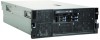
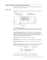
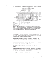
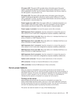
Rear view The following illustration shows the connectors and LEDs on the rear of the server. Power-on LED Gigabit Ethernet 2 LED Gigabit Ethernet 2 System-error LED Locator LED USB SAS Gigabit Ethernet 1 LED Gigabit Ethernet 1 Remote Supervisor Adapter II Power supply 1 AC power DC power Powersupply error Power supply 2 System serial SMP Expansion Port 1 link LED SMP Expansion Port 1 SMP Expansion Port 2 link LED SMP Expansion Port 2 SMP Expansion Port 3 SMP Expansion Port 3 link LED Power-on LED: When this LED is lit and not flashing, it indicates that the server is turned on. When this LED is flashing, it indicates that the server is turned off and still connected to an ac power source. When this LED is off, it indicates that ac power is not present or the power supply or the LED itself has failed. Note: If this LED is off, it does not mean that there is no electrical power in the server. The LED might be burned out. To remove all electrical power from the server, you must disconnect the power cords from the electrical outlets. Locator LED: Use this LED to visually locate the server among other servers. You can use IBM Director to light this LED remotely or press the locator button to light the LED manually. This LED is also lit during startup. System-error LED: When this LED is lit, it indicates that a system error has occurred. An LED on the light path diagnostics panel is also lit to help isolate the error. Gigabit Ethernet 2 LED: When this LED flashes, it indicates that there is activity between the server and the network. When this LED is lit continuously, it indicates that there is an active connection on the Ethernet port. Gigabit Ethernet 2 connector: Use this connector to connect the server to a network. Gigabit Ethernet 1 LED: When this LED flashes, it indicates that there is activity between the server and the network. When this LED is lit continuously, it indicates that there is an active connection on the Ethernet port. Gigabit Ethernet 1 connector: Use this connector to connect the server to a network. This connector is shared with the baseboard management controller Chapter 1. The System x3850 M2 and System x3950 M2 server 13
-
 1
1 -
2
-
3
-
4
-
5
-
6
-
7
-
8
-
9
-
10
-
11
-
12
-
13
-
14
-
15
-
16
-
17
-
18
-
19
-
 20
20 -
 21
21 -
 22
22 -
 23
23 -
 24
24 -
 25
25 -
 26
26 -
 27
27 -
 28
28 -
 29
29 -
 30
30 -
31
-
32
-
33
-
34
-
35
-
36
-
37
-
38
-
39
-
40
-
41
-
42
-
43
-
44
-
45
-
46
-
47
-
48
-
49
-
50
-
51
-
52
-
53
-
54
-
55
-
56
-
57
-
58
-
59
-
60
-
61
-
62
-
63
-
64
-
65
-
66
-
67
-
68
-
69
-
70
-
71
-
72
-
73
-
74
-
75
-
76
-
77
-
78
-
79
-
80
-
81
-
82
-
83
-
84
-
85
-
86
-
87
-
88
-
89
-
90
-
91
-
92
-
93
-
94
-
95
-
96
-
97
-
98
-
99
-
100
-
101
-
102
 |
 |
