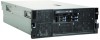
IBM 72336RU User Manual - Page 27
Server power features, Turning on the server
 |
View all IBM 72336RU manuals
Add to My Manuals
Save this manual to your list of manuals |
Page 27 highlights
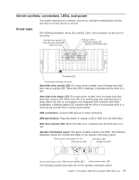
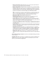
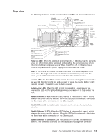
AC power LED: This green LED provides status information about the power supply. During typical operation, both the ac and dc power LEDs are lit. For any other combination of LEDs, see the Problem Determination and Service Guide on the IBM System x Documentation CD. DC power LED: This green LED provides status information about the power supply. During typical operation, both the ac and dc power LEDs are lit. For any other combination of LEDs, see the Problem Determination and Service Guide on the IBM System x Documentation CD. Power-supply error LED: When this amber LED is lit, it indicates that there is an error condition within the power supply. For more information, see the Problem Determination and Service Guide on the IBM System x Documentation CD. Power supply 2 connector: Connect the power cord to this connector. SMP Expansion Port 3 connector: Use this connector to connect the server to other servers to form multi-node configurations (requires scalability enablement). SMP Expansion Port 3 link LED: When this LED is lit, it indicates that there is an active connection on SMP Expansion Port 3. SMP Expansion Port 1 link LED: When this LED is lit, it indicates that there is an active connection on SMP Expansion Port 1. SMP Expansion Port 1 connector: Use this connector to connect the server to other servers to form multi-node configurations (requires scalability enablement). SMP Expansion Port 2 link LED: When this LED is lit, it indicates that there is an active connection on SMP Expansion Port 2. SMP Expansion Port 2 connector: Use this connector to connect the server to other servers to form multi-node configurations (requires scalability enablement). System serial connector: Connect a 9-pin serial device to this connector. SAS connector: Connect an internal SAS device to this connector. USB connectors: Connect USB devices to these connectors. Server power features When the server is connected to an ac power source but is not turned on, the operating system does not run, and all core logic except for the service processor is shut down; however, the server can respond to requests from the service processor, such as a remote request to turn on the server. The power-on LED flashes to indicate that the server is connected to ac power but not turned on. Turning on the server Approximately 20 seconds after the server is connected to ac power, the power-control button becomes active, and one or more fans might start running to provide cooling while the server is connected to power. You can turn on the server and start the operating system by pressing the power-control button. The server can also be turned on in any of the following ways: Chapter 1. The System x3850 M2 and System x3950 M2 server 15
-
 1
1 -
2
-
3
-
4
-
5
-
6
-
7
-
8
-
9
-
10
-
11
-
12
-
13
-
14
-
15
-
16
-
17
-
18
-
19
-
20
-
21
-
 22
22 -
 23
23 -
 24
24 -
 25
25 -
 26
26 -
 27
27 -
 28
28 -
 29
29 -
 30
30 -
 31
31 -
 32
32 -
33
-
34
-
35
-
36
-
37
-
38
-
39
-
40
-
41
-
42
-
43
-
44
-
45
-
46
-
47
-
48
-
49
-
50
-
51
-
52
-
53
-
54
-
55
-
56
-
57
-
58
-
59
-
60
-
61
-
62
-
63
-
64
-
65
-
66
-
67
-
68
-
69
-
70
-
71
-
72
-
73
-
74
-
75
-
76
-
77
-
78
-
79
-
80
-
81
-
82
-
83
-
84
-
85
-
86
-
87
-
88
-
89
-
90
-
91
-
92
-
93
-
94
-
95
-
96
-
97
-
98
-
99
-
100
-
101
-
102
 |
 |
