IBM 72336RU User Manual - Page 60
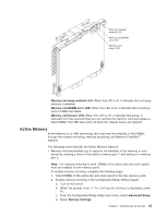
While you hold the retention levers open, lift the memory card out of
 |
View all IBM 72336RU manuals
Add to My Manuals
Save this manual to your list of manuals |
Page 60 highlights
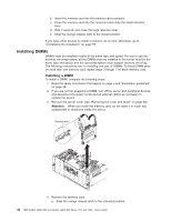
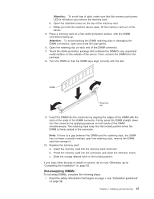
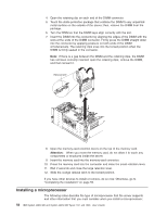
Attention: Static electricity that is released to internal server components when the server is powered-on might cause the server to halt, which might result in the loss of data. To avoid this potential problem, always use an electrostatic-discharge wrist strap or other grounding system when you work inside the server with the power on. 2. Remove the server cover (see "Removing the cover and bezel" on page 30). 3. Make sure that the memory hot-swap enabled LED is lit. If the LED is not lit, enable memory mirroring (see "Active Memory" on page 43). Release latch 4. Remove the memory card: a. Slide the orange release latch to the unlocked position. Attention: v When you move the memory card, do not allow it to touch any components or structures inside the server. v To avoid loss of data, make sure that the memory port power LED is off before you remove the memory card. b. Open the retention levers on the top of the memory card. c. While you hold the retention levers open, lift the memory card out of the server. 5. Place a memory card on a flat, static-protective surface, with the DIMM connectors facing up. Attention: To avoid breaking the DIMM retaining clips or damaging the DIMM connectors, open and close the clips gently. 6. Open the retaining clip on each end of the DIMM connector and remove the DIMM or DIMMs that you are replacing. 7. Touch the static-protective package that contains the DIMM to any unpainted metal surface on the outside of the server; then, remove the DIMM from the package. 8. Turn the DIMM so that the DIMM keys align correctly with the slot. 48 IBM System x3850 M2 and System x3950 M2 Types 7141 and 7233: User's Guide
-
 1
1 -
2
-
3
-
4
-
5
-
6
-
7
-
8
-
9
-
10
-
11
-
12
-
13
-
14
-
15
-
16
-
17
-
18
-
19
-
20
-
21
-
22
-
23
-
24
-
25
-
26
-
27
-
28
-
29
-
30
-
31
-
32
-
33
-
34
-
35
-
36
-
37
-
38
-
39
-
40
-
41
-
42
-
43
-
44
-
45
-
46
-
47
-
48
-
49
-
50
-
51
-
52
-
53
-
54
-
 55
55 -
 56
56 -
 57
57 -
 58
58 -
 59
59 -
 60
60 -
 61
61 -
 62
62 -
 63
63 -
 64
64 -
 65
65 -
66
-
67
-
68
-
69
-
70
-
71
-
72
-
73
-
74
-
75
-
76
-
77
-
78
-
79
-
80
-
81
-
82
-
83
-
84
-
85
-
86
-
87
-
88
-
89
-
90
-
91
-
92
-
93
-
94
-
95
-
96
-
97
-
98
-
99
-
100
-
101
-
102
 |
 |
