Icom M802 Instruction Manual - Page 13
Rear panel- Main unit, Microphone HM-135
 |
View all Icom M802 manuals
Add to My Manuals
Save this manual to your list of manuals |
Page 13 highlights
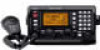
I Rear panel- Main unit 2 PANEL DESCRIPTION 2 q we r t q TUNER CONTROL SOCKET (pgs. 54, 56, 61) Connects a control cable to an optional antenna tuner. A female connector kit is supplied for external antenna tuner connection. w GROUND TERMINAL IMPORTANT! Connects a ship's (or vehicle's) ground. See pages 55 and 63-65 for details. e ANTENNA CONNECTOR 1 (pgs. 54, 56) Connects a 50 Ω HF band antenna via a 50 Ω matched coaxial cable with a PL-259 plug for both transmit and receive operation. r ANTENNA CONNECTOR 2 (pgs. 54, 56) Connects a 50 Ω HF band antenna via a 50 Ω matched coaxial cable with a PL-259 plug for DSC receiver. t DC POWER SOCKET (p. 54, 61) Accepts 13.6 V DC through the supplied DC power cable. ✔ For detailed "ANTENNA AND GROUNDING CONSIDERATIONS," see pages 63 to 65. I Microphone (HM-135) q Microphone w e q PTT SWITCH [PTT] Push and hold to transmit; release to receive. w UP/DOWN SWITCHES Push either switch to change the operating channel, frequency, etc. e USER PROGRAMMABLE SWITCH [P] Push to activate or deactivate a function, selected in initial set mode (p. 51). 5
-
 1
1 -
2
-
3
-
4
-
5
-
6
-
7
-
 8
8 -
 9
9 -
 10
10 -
 11
11 -
 12
12 -
 13
13 -
 14
14 -
 15
15 -
 16
16 -
 17
17 -
 18
18 -
19
-
20
-
21
-
22
-
23
-
24
-
25
-
26
-
27
-
28
-
29
-
30
-
31
-
32
-
33
-
34
-
35
-
36
-
37
-
38
-
39
-
40
-
41
-
42
-
43
-
44
-
45
-
46
-
47
-
48
-
49
-
50
-
51
-
52
-
53
-
54
-
55
-
56
-
57
-
58
-
59
-
60
-
61
-
62
-
63
-
64
-
65
-
66
-
67
-
68
-
69
-
70
-
71
-
72
-
73
-
74
-
75
-
76
-
77
-
78
 |
 |
