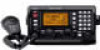
Icom M802 Instruction Manual - Page 69
Connector information
 |
View all Icom M802 manuals
Add to My Manuals
Save this manual to your list of manuals |
Page 69 highlights
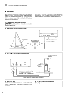
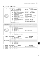
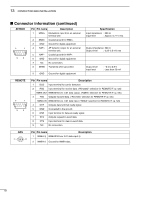
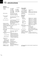
13 CONFECTION AND INSTALLATION I Connector information ACC Pin Pin name Description 1 CWK CW and FSK keying input. 2 AF GND Ground line for AF signal. Input/output pin. 3 SEND Goes to ground when transmitting. When grounded, transmits. * 76 381 54 2 4 MOD Modulator input. Usable when pin 3 is grounded. 5 AF AF detector output. Fixed, regardless of [VOL] position. 6 NC No connection 7 13.6 V 13.6 V output when power is ON. 8 ALC ALC voltage input. * DC GND Common ground. Input level Specification : Less than 0.6 V for transmit Ground level Input current : -0.5 to 0.8 V : Less than 20 mA Input impedance : 5 kΩ Input level : Approx. 100 mV rms Output impedance: 4.7 kΩ Output level : 100-300 mV rms Output current : max. 1 A Control voltage : -3 to 0 V Input impedance : More than 10 kΩ MICROPHONE Pin Pin name Description 1 MIC+ Audio input from the mic element. 2 NC No connection qu wiy ert 3 AF1 AF output controlled with [VOL]. 4 AF2 Ground for AF1. 5 PTT PTT switch input. 6 GND Connected to the ground. 7 MIC- Coaxial ground for MIC+. 8 AF- Coaxial ground for AF1 and AF2. Specification Input impedance : 2.4 kΩ When grounded, transmits. TUNER 123456 Pin Pin name Description 1 KEY Key signal input. 2 START Start/through signal output 3 13.6V 13.6 V output 4 E Negative terminal 5 NC No connection 6 NC No connection DC 13.6V 123 456 Pin Pin name Description 1-3 + DC input +. 4-6 _ DC input _. Specification -0.5 to 0.8 V during tuning Specification Max. power consumption 30 A typical. 13 61
-
 1
1 -
2
-
3
-
4
-
5
-
6
-
7
-
8
-
9
-
10
-
11
-
12
-
13
-
14
-
15
-
16
-
17
-
18
-
19
-
20
-
21
-
22
-
23
-
24
-
25
-
26
-
27
-
28
-
29
-
30
-
31
-
32
-
33
-
34
-
35
-
36
-
37
-
38
-
39
-
40
-
41
-
42
-
43
-
44
-
45
-
46
-
47
-
48
-
49
-
50
-
51
-
52
-
53
-
54
-
55
-
56
-
57
-
58
-
59
-
60
-
61
-
62
-
63
-
 64
64 -
 65
65 -
 66
66 -
 67
67 -
 68
68 -
 69
69 -
 70
70 -
 71
71 -
 72
72 -
 73
73 -
 74
74 -
75
-
76
-
77
-
78
 |
 |
