Icom M802 Instruction Manual - Page 61
Connection And Installation
 |
View all Icom M802 manuals
Add to My Manuals
Save this manual to your list of manuals |
Page 61 highlights
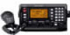
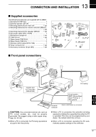
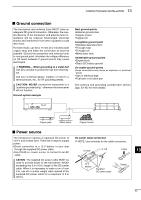
13 CONNECTION AND INSTALLATION I Supplied accessories The following accessories are supplied with IC-M802. q Microphone (HM-135 1 w External speaker (SP-24 1 q e Mounting bracket kit for main unit 1 set r Mounting bracket kit for remote controller (MB-81) 1 set r t Mounting bracket kit for speaker (MB-82) ... 1 set y DC power cable (OPC-1107A 1 u Microphone hanger kit 1 set i Cable tie set 1 set o Spare fuses (FGB 30 A 1 u !0 Spare fuses (FGB 5 A 2 !1 Remote control cable (OPC-1106 1 !1 !2 Tuner connector kit 1 set !3 Accessory connector (8-pin DIN 1 set w e t y o !0 i !2 !3 I Front panel connections Position and UTC time data (NMEA0183) CAUTION: Any connected external unit, such as PC, e-mail modem, etc., must be properly grounded. We suggest using a wide copper strap. (pgs. 55, 63-65) ➥ When a PC is connected, the PC being operated at any given time has priority. 12 V battery E-mail modem, NBDP (Narrow Band Direct Printing), or FAX systems Personal computer (when e-mail modem is connected) 12 13 ➥ When a PC is connected, the controller not being operated is inhibited for a specified time after the PC is operated. This time can be programmed by your dealer. The default inhibit time is 5 sec. ➥ When a PC is connected, operating the PC automatically updates settings on the controller. 53
-
 1
1 -
2
-
3
-
4
-
5
-
6
-
7
-
8
-
9
-
10
-
11
-
12
-
13
-
14
-
15
-
16
-
17
-
18
-
19
-
20
-
21
-
22
-
23
-
24
-
25
-
26
-
27
-
28
-
29
-
30
-
31
-
32
-
33
-
34
-
35
-
36
-
37
-
38
-
39
-
40
-
41
-
42
-
43
-
44
-
45
-
46
-
47
-
48
-
49
-
50
-
51
-
52
-
53
-
54
-
55
-
 56
56 -
 57
57 -
 58
58 -
 59
59 -
 60
60 -
 61
61 -
 62
62 -
 63
63 -
 64
64 -
 65
65 -
 66
66 -
67
-
68
-
69
-
70
-
71
-
72
-
73
-
74
-
75
-
76
-
77
-
78
 |
 |
