Icom M802 Instruction Manual - Page 63
Ground connection, Power source
 |
View all Icom M802 manuals
Add to My Manuals
Save this manual to your list of manuals |
Page 63 highlights
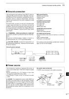
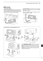
13 CONFECTION AND INSTALLATION I Ground connection The transceiver and antenna tuner MUST have an adequate RF ground connection. Otherwise, the overall efficiency of the transceiver and antenna tuner installation will be reduced. Electrolysis, electrical shocks and interference from other equipment could also occur. For best results, use 50 or 75 mm (2 or 3 inches) wide copper strap and make the connection as short as possible. Ground the transceiver and antenna tuner to one ground point, otherwise the voltage difference (in RF level) between 2 ground points may cause electrolysis. R WARNING- When grounding to a metal hull Use Zinc anodes to protect the hull from electrolysis. Ask your technical dealer, installer or refer to a technical book, etc., for RF grounding details. CAUTION: NEVER connect the transceiver to a "positive-grounded ship," otherwise the transceiver will not function. Ground system example Best ground points • External ground plate • Copper screen • Copper foil Acceptable ground point • Stainless steel stanchion • Through mast • Through hull • Metal water tank Undesirable ground points • Engine block • Ship's DC battery ground Un-usable ground points (these connections may cause an explosion or electrical shock) • Gas or electrical pipe • Fuel tank or oil-catch pan See antenna and grounding consideration section (pgs. 63-65) for more details. Copper pipe Metal object ;;;;yyyy;;;;yyyy;;;;yyyy;;;;yyyy;;;;yyyy;;;;yyyy Copper screen I Power source The transceiver requires a regulated DC power of DC power cable connection 13.6 V and at least 30 A. There are 2 ways to supply power: NOTE: Use terminals for the cable connection. •Direct connection to a 12 V battery in your ship through the supplied DC power cable. • Use PS-60 DC POWER SUPPLY to connect to an AC _ black + red Crimp 13 outlet. CATION: The supplied DC power cable MUST be used to provide power to the transceiver. AVOID exceeding the 3 m (10 ft.) length of the DC power cable. When it is necessary to make a run of over 3 m, use #6 or similar weight cable instead of the supplied DC power cable for a maximum of 6 m (20 ft.). 12 V battery Supplied DC power cable Solder 55
-
 1
1 -
2
-
3
-
4
-
5
-
6
-
7
-
8
-
9
-
10
-
11
-
12
-
13
-
14
-
15
-
16
-
17
-
18
-
19
-
20
-
21
-
22
-
23
-
24
-
25
-
26
-
27
-
28
-
29
-
30
-
31
-
32
-
33
-
34
-
35
-
36
-
37
-
38
-
39
-
40
-
41
-
42
-
43
-
44
-
45
-
46
-
47
-
48
-
49
-
50
-
51
-
52
-
53
-
54
-
55
-
56
-
57
-
 58
58 -
 59
59 -
 60
60 -
 61
61 -
 62
62 -
 63
63 -
 64
64 -
 65
65 -
 66
66 -
 67
67 -
 68
68 -
69
-
70
-
71
-
72
-
73
-
74
-
75
-
76
-
77
-
78
 |
 |
