Icom M802 Instruction Manual - Page 73
Summary - weather fax
 |
View all Icom M802 manuals
Add to My Manuals
Save this manual to your list of manuals |
Page 73 highlights
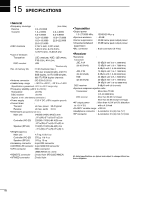
14 ANTENNA AND GROUNDING CONSIDERATIONS terline ground system and attached directly to each piece of low and high frequency radio gear. While this may also seem to be an insurmountable problem in running foil, rather than wire, foil handles quite nicely, even in tight places. The foil is easily soldered to the below waterline ground system, and then routed up the side of the hull into the area of the NAV station. It may be glassed into the hull, painted over, glued in, or even left resting on the side of the hull. The foil may be bent in order to accomplish a 90-degree turn. If the foil must absolutely pass through a small hole, it may be rolled up in a not-so-tight configuration and squeezed through the orifice. Avoid a concentric type, for that type tends to cancel oscillating radio frequencies. Flat is best. There are several sticky marine compounds that will allow the foil to adhere to the underside of a hatch, or to the side of a hull. Almost anything will work, and there is little danger of any substantial amounts of voltage developing on your ground foil run. The ground foil and your complete RF ground system, which run inside the hull, also will not substantially change your corrosion exposure to the seawater. Galvanic corrosion problems occur when dissimilar metals are immersed in seawater. The ground system is not actually immersed, its coupling is only capacitive. Electrolysis is another form of corrosion where stray currents may begin to eat up underwater metals. Good wiring techniques for your 12-volt system independent of your RF ground system will eliminate electrolysis. Now let's get back to finding a spot to terminate that threeinch wide copper foil that emanates from the below waterline ground system. Most manufacturers of Loran weather fax and marine single sideband sets don't provide an easy way of adding ground foil to the stern end of their electronics! The best method is to run the foil up to the back of the equipment and use existing sheet metal screws to make a firm connection. Where a ground post stud with nuts and a washer are provided, all the better- run the foil up to the stud, double it back on itself several times for strength, punch a hole in it, and then make the connection. Never negate all your hard work of running the foil by using a small jumper wire to interconnect the foil to the radio set-up. You will be putting a "weak link" in your ground system at radio frequencies. We usually accordion up the excess foil in back of the equipment so that we might remove the equipment for servicing with the foil attached. If you put the bends in the right spot, the foil will resume its natural collapsed state when the equipment is put back in place. Watch out for the sharp corners on the ground foil, they are capable of piercing through the plastic protective covering on electrical wires. Make sure that red and black voltage carrying wires are not allowed to rub up against the side of the ground foil. We usually ground everything with foil at the navigation station. This would include the casing of the wind and speed equipment, pilot control box, GPS, sideband, radar, VHF, and just about everything else that lights up. The more grounding you provide for your central electronics, the less problems you will have with stray RF. The ground foil must also run to remote tuners. This includes the tuner on your Loran antenna set-up as well as the ICOM single sideband tuner that's usually several feet away from the equipment. These tuners may be all the way back aft, adding another dimension to your ground foil run. It's best to run the foil from the RF ground source directly to your tuner, rather than stringing everything out in series like Christmas tree lights. Now picture one ground foil run from the keel bolt to the electronics, and a second ground foil run from the keel bolt back aft to the sideband tuner and your stern-mounted Loran whip. These tuner ground circuits are mandatory for any type of reliable operation. If you try to run an ICOM sideband set with a remote tuner that is undergrounded, you stand the chance of not only burning up your equipment, but also damaging other electronics onboard with stray RF. If it's not easy to run ground foil from your central below the waterline ground source back aft, then try to figure out another way to do it. It has to be done! You can also pick up additional ground counterpoise surface area by adding substantial metals along the way in your copper foil run. Stainless steel hose clamps make it easy to pick up through-hull bronze fittings, water tanks, copper hydraulic lines, and anything else that may give you some additional underwater surface area. Mariners with sailboats with poured incapsulated lead keels as well as metal hull vessels have the easiest time in obtaining a good ground counterpoise. If the keel is visible, a second nut on the exposed thread will anchor on the ground foil. We usually seal this connection to prevent deterioration from the bilge water. It may also be recommended by local experts to tie in the aluminum mast to this close proximity keel bolt for lightning protection. The run from the mast to the keel bolt must be smooth, direct, and without sharp turns in order to pass lightning energy effectively into the underwater lead. Again, consult local lightning experts. Steel-hulled vessels are easily attached to with foil by scraping away any protective coating from the hull, and making a low resistant good surface area contact. Again, seal this connection well. Non-metal hull or keel boats require yards and yards of foil to be run below the waterline, anywhere you can, and picking up any other large below the waterline tanks and tubes. SUMMARY If you follow these steps, you will have an outstanding single sideband signal that can be heard around the world. The difference between a good and bad ground is easily noticed on transmission as well as reception. Since your ground counterpoise is actually a part of your complete antenna system, pay just as much attention to RF grounding as you did to putting up that white fiber glass whip or installing to your insulated backstay. 14 65
-
 1
1 -
2
-
3
-
4
-
5
-
6
-
7
-
8
-
9
-
10
-
11
-
12
-
13
-
14
-
15
-
16
-
17
-
18
-
19
-
20
-
21
-
22
-
23
-
24
-
25
-
26
-
27
-
28
-
29
-
30
-
31
-
32
-
33
-
34
-
35
-
36
-
37
-
38
-
39
-
40
-
41
-
42
-
43
-
44
-
45
-
46
-
47
-
48
-
49
-
50
-
51
-
52
-
53
-
54
-
55
-
56
-
57
-
58
-
59
-
60
-
61
-
62
-
63
-
64
-
65
-
66
-
67
-
 68
68 -
 69
69 -
 70
70 -
 71
71 -
 72
72 -
 73
73 -
 74
74 -
 75
75 -
 76
76 -
 77
77 -
 78
78
 |
 |