Icom M802 Instruction Manual - Page 62
Rear panel connections
 |
View all Icom M802 manuals
Add to My Manuals
Save this manual to your list of manuals |
Page 62 highlights
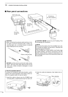
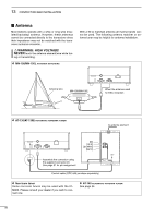
13 CONFECTION AND INSTALLATION I Rear panel connections Optional AT-140 HF antenna (for DSC reception) Grounding (see pgs. 55, 63-65) Grounding (see pgs. 55, 63-65) OPC-1147 (10 m; 32.8 ft) CAUTION: • After connecting the antenna cable and tuner control cable, cover the connectors with a rubber vulcanizing tape, etc., as shown below, to prevent water seeping into the connector. Rubber vulcanizing tape 12 V battery CAUTION: NEVER connect to a 24 V battery. This will damage the transceiver. NOTE: Disconnect the battery from the IC-M802 main unit, or charge the battery during anchor, otherwise the battery may be exhausted. The IC-M802 has a high-stability oven-heater type crystal oscillator, and when connected to the DC power socket directly, it keeps its temperature to at the specified level even if the transceiver power has turned OFF. • DO NOT pull the antenna and control cable receptacles. This may cause cable disconnection (in the tuner unit), inside connector damaged or a bad connection. ✔ Use the supplied cable tie To prevent an accidental cable disconnection, particularly for the external speaker and remote control cables, the supplied cable tie may be helpful. q Install the cable tie (base) onto the IC-M802 main unit side panel, or desired place near the main unit. w Insert the cable tie (fastener), then fasten the cables. When releasing: Up Pull 54
-
 1
1 -
2
-
3
-
4
-
5
-
6
-
7
-
8
-
9
-
10
-
11
-
12
-
13
-
14
-
15
-
16
-
17
-
18
-
19
-
20
-
21
-
22
-
23
-
24
-
25
-
26
-
27
-
28
-
29
-
30
-
31
-
32
-
33
-
34
-
35
-
36
-
37
-
38
-
39
-
40
-
41
-
42
-
43
-
44
-
45
-
46
-
47
-
48
-
49
-
50
-
51
-
52
-
53
-
54
-
55
-
56
-
 57
57 -
 58
58 -
 59
59 -
 60
60 -
 61
61 -
 62
62 -
 63
63 -
 64
64 -
 65
65 -
 66
66 -
 67
67 -
68
-
69
-
70
-
71
-
72
-
73
-
74
-
75
-
76
-
77
-
78
 |
 |
