JVC SR-VD400US Instruction Manual - Page 66
EDITING, i.LINK/DV Connections
 |
View all JVC SR-VD400US manuals
Add to My Manuals
Save this manual to your list of manuals |
Page 66 highlights
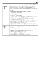
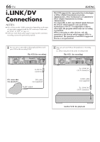
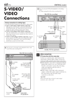
66 EN i.LINK/DV Connections NOTES: ● You cannot use the i.LINK connection depending on the type of camcorder equipped with the DV connector. In this case, set "LINC" to "OFF" (੬ pg. 62). ● If the 44.1 kHz PCM audio signal is input via DV connector, recording cannnot be performed properly. EDITING This VCR supports the copy protection technologies of DTLA (Digital Transmission Licensing Administrator). These technologies are admitted by DTLA (Digital Transmission Licensing Administrator). It is impossible to dub copy-limited signals between the devices which supports copy protection technologies of DTLA. It is impossible to dub to other tapes the program which only one recording is permitted. When connecting to other devices, only the operation of the devices which supports DTLA is guaranteed. The operation of non-DTLA-supported devices is not guaranteed. A You can use a camcorder as the playback device and your VCR as the recording VCR. This VCR (for recording) CABLE BOX REMOTE PAUSE/ AV COMPULINK OUT Y PB/CB S VIDEO PR/CR COMPONENT VIDEO OUT IN IN(L-1) S VIDEO R AUDIO L VIDEO R AUDIO L VIDEO IN(L-2) VHF/UHF ANTENNA IN ANTENNA OUT i.LINK IN/OUT DV IN S400 DIGITAL OUT OPTICAL PCM/DOLBY DIGITAL D THEATER REGION 1 To DV IN connector DV camcorder (for playback) DV cable (not supplied) To DV output B You can use your VCR as the playback or recording VCR. Ex. When using this VCR as the recording VCR This VCR (for recording) CABLE BOX REMOTE PAUSE/ AV COMPULINK OUT Y PB/CB S VIDEO PR/CR COMPONENT VIDEO OUT IN IN(L-1) S VIDEO R AUDIO L VIDEO R AUDIO L VIDEO IN(L-2) VHF/UHF ANTENNA IN ANTENNA OUT i.LINK IN/OUT DV IN S400 DIGITAL OUT OPTICAL PCM/DOLBY DIGITAL D THEATER REGION 1 To i.LINK IN/ OUT connector i.LINK cable (not supplied) To i.LINK IN/ OUT connector Another VCR (for playback)
-
 1
1 -
2
-
3
-
4
-
5
-
6
-
7
-
8
-
9
-
10
-
11
-
12
-
13
-
14
-
15
-
16
-
17
-
18
-
19
-
20
-
21
-
22
-
23
-
24
-
25
-
26
-
27
-
28
-
29
-
30
-
31
-
32
-
33
-
34
-
35
-
36
-
37
-
38
-
39
-
40
-
41
-
42
-
43
-
44
-
45
-
46
-
47
-
48
-
49
-
50
-
51
-
52
-
53
-
54
-
55
-
56
-
57
-
58
-
59
-
60
-
 61
61 -
 62
62 -
 63
63 -
 64
64 -
 65
65 -
 66
66 -
 67
67 -
 68
68 -
 69
69 -
 70
70 -
 71
71 -
72
-
73
-
74
-
75
-
76
-
77
-
78
-
79
-
80
-
81
-
82
-
83
-
84
-
85
-
86
-
87
-
88
-
89
-
90
-
91
-
92
 |
 |
