JVC SR-VD400US Instruction Manual - Page 8
S-VIDEO Connection, Component Video Connection, INSTALLING YOUR NEW VCR cont.
 |
View all JVC SR-VD400US manuals
Add to My Manuals
Save this manual to your list of manuals |
Page 8 highlights
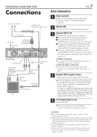
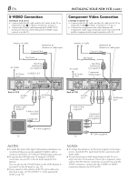
8 EN S-VIDEO Connection CONNECT VCR TO TV a- Connect both the RF cable and the AV cables to the TV as explained in step 3 of "Basic Connection" (੬ pg. 7). b- Connect the S-Video cable between the S VIDEO OUT terminal on the rear of the VCR and the S-VIDEO input connector on the TV. INSTALLING YOUR NEW VCR (cont.) Component Video Connection CONNECT VCR TO TV a- Connect both the RF cable and the AV cables to the TV as explained in step 3 of "Basic Connection" (੬ pg. 7). b- Connect the component video cable between the Component video output terminals on the rear of the VCR and the component video input terminals on the TV. Antenna or Cable ANTENNA IN (Antenna or cable input) Coaxial Cable Antenna or Cable ANTENNA IN (Antenna or cable input) Coaxial Cable Flat Feeder AC Outlet Matching Transformer (not supplied) AC Power S VIDEO OUT Cord CABLE BOX REMOTE PAUSE/ AV COMPULINK OUT Y PB/CB S VIDEO PR/CR COMPONENT VIDEO OUT IN IN(L-1) S VIDEO R AUDIO L VIDEO R AUDIO L VIDEO IN(L-2) VHF/UHF ANTENNA IN ANTENNA OUT i.LINK IN/OUT DV IN S400 DIGITAL OUT OPTICAL PCM/DOLBY DIGITAL D THEATER REGION 1 Back of VCR AUDIO OUT ANTENNA OUT Flat Feeder AC Outlet AC Power Cord Matching Transformer (not supplied) Component Video Output CABLE BOX REMOTE PAUSE/ AV COMPULINK OUT Y PB/CB S VIDEO PR/CR COMPONENT VIDEO OUT IN IN(L-1) S VIDEO R AUDIO L VIDEO R AUDIO L VIDEO IN(L-2) VHF/UHF ANTENNA IN ANTENNA OUT i.LINK IN/OUT DV IN S400 DIGITAL OUT OPTICAL PCM/DOLBY DIGITAL D THEATER REGION 1 Back of VCR AUDIO OUT ANTENNA OUT Audio Cable (supplied) S-Video Cable (supplied) S-VIDEO IN Audio Cable (supplied) Component Video Cable (not supplied) RF Cable (supplied) TV RF Cable (supplied) TV NOTES: ● To make the most of the Super VHS picture performance we recommend that you use the supplied S-VIDEO cable to connect your VCR to a TV with an S-VIDEO input connector. ● To operate the VCR with your TV using the S-VIDEO connection, set your TV to the AV mode using the TV's Remote. You can also use the TV/VCR button on the VCR's Remote to set your TV to the AV mode (੬ pg. 70). ● If you cannot see the pictures on the TV screen when you play back a tape, set "TV OUTPUT 1" to the appropriate mode (੬ pg. 58). NOTES: ● To change the settings or set the timer program on the menu screen, switch the TV's input mode for the connection with Audio cable. ● To view the picture of 480i image format on the TV, or to select and view TV broadcast, connect the component video cable to the TV's Y/CB/CR connectors. If your TV has only the Y/PB/PR connectors, connect also the S-VIDEO or VIDEO connectors between the VCR and TV.
-
 1
1 -
2
-
 3
3 -
 4
4 -
 5
5 -
 6
6 -
 7
7 -
 8
8 -
 9
9 -
 10
10 -
 11
11 -
 12
12 -
 13
13 -
14
-
15
-
16
-
17
-
18
-
19
-
20
-
21
-
22
-
23
-
24
-
25
-
26
-
27
-
28
-
29
-
30
-
31
-
32
-
33
-
34
-
35
-
36
-
37
-
38
-
39
-
40
-
41
-
42
-
43
-
44
-
45
-
46
-
47
-
48
-
49
-
50
-
51
-
52
-
53
-
54
-
55
-
56
-
57
-
58
-
59
-
60
-
61
-
62
-
63
-
64
-
65
-
66
-
67
-
68
-
69
-
70
-
71
-
72
-
73
-
74
-
75
-
76
-
77
-
78
-
79
-
80
-
81
-
82
-
83
-
84
-
85
-
86
-
87
-
88
-
89
-
90
-
91
-
92
 |
 |
