Lantronix SGX 5150 User Guide - Page 23
Hardware Components, Front Panel, Back Panel, Serial Interface
 |
View all Lantronix SGX 5150 manuals
Add to My Manuals
Save this manual to your list of manuals |
Page 23 highlights
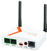
Hardware Components Front Panel 3: Installation of the SGX 5150 Figure 3-1 Front Panel LED Status WLAN Signal Table 3-2 SGX 5150 LEDs and Descriptions Description No IP obtained from eth0 network: L, L, S, S, S No IP obtained from wlan0 network: L, L, L, S, S, S No IP obtained from the usb0 network: L, L, L, L, L, S No eth0 link: L, L, S, S No wlan link: L, L, L, S, S No usb0 link: L, L, L, L, L, S, S The wlan indicator light and color pattern indicates the wlan status according to Table 3-10 and Table 3-11 and also reflects the WPS status according to Table 3-13. See Table 3-10 and Table 3-11 for signal strength indication information. Back Panel Figure 3-3 Back Panel Serial Interface One or two serial ports are available for the SGX 5150. Data rates can be configured for speeds between 300 and 921 kbaud. Hardware protocol options include the following: Two RJ45 RS232 Serial Ports, or Two RJ45 Multi-protocol RS232/422/485 ports, or One RJ45 RS232 Serial Port, and one RJ45 Multi-protocol RS232/422/485 port, or One RJ45 RS232 Serial Port, or One RJ45 Multi-protocol RS232/422/485 port SGX 5150 IoT Device Gateway User Guide 23
-
 1
1 -
2
-
3
-
4
-
5
-
6
-
7
-
8
-
9
-
10
-
11
-
12
-
13
-
14
-
15
-
16
-
17
-
 18
18 -
 19
19 -
 20
20 -
 21
21 -
 22
22 -
 23
23 -
 24
24 -
 25
25 -
 26
26 -
 27
27 -
 28
28 -
29
-
30
-
31
-
32
-
33
-
34
-
35
-
36
-
37
-
38
-
39
-
40
-
41
-
42
-
43
-
44
-
45
-
46
-
47
-
48
-
49
-
50
-
51
-
52
-
53
-
54
-
55
-
56
-
57
-
58
-
59
-
60
-
61
-
62
-
63
-
64
-
65
-
66
-
67
-
68
-
69
-
70
-
71
-
72
-
73
-
74
-
75
-
76
-
77
-
78
-
79
-
80
-
81
-
82
-
83
-
84
-
85
-
86
-
87
-
88
-
89
-
90
-
91
-
92
-
93
-
94
-
95
-
96
-
97
-
98
-
99
-
100
-
101
-
102
-
103
-
104
-
105
-
106
-
107
-
108
-
109
-
110
-
111
-
112
-
113
-
114
-
115
-
116
-
117
-
118
-
119
-
120
-
121
-
122
-
123
-
124
-
125
-
126
-
127
-
128
-
129
 |
 |
