Lantronix SGX 5150 User Guide - Page 28
transmitted or received as intended.
 |
View all Lantronix SGX 5150 manuals
Add to My Manuals
Save this manual to your list of manuals |
Page 28 highlights
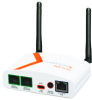
3: Installation of the SGX 5150 3. Mount or place the device securely. 4. Supply power to the SGX 5150 and connect it to the user device by using the supplied tape A to type C USB cable. As soon as you plug the device into power, the device powers up automatically, the self-test begins, and LEDs would indicate the device's status. Note: The SGX 5150 supports a power range of 9 to 30 VDC and can be powered up via the barrel-power adapter or USB port. 5. Via the computer connected on the same network, you can follow one of two paths to device discovery and initial network configuration as outlined below. Note: Antennas must be installed prior to powering on the unit. Do not remove or connect the antennas while the unit power is on or proper wireless signals may not be transmitted or received as intended. Figure 3-14 SGX 5150 Dimensions in Inches (in) and Millimeters (mm) SGX 5150 IoT Device Gateway User Guide 28
-
 1
1 -
2
-
3
-
4
-
5
-
6
-
7
-
8
-
9
-
10
-
11
-
12
-
13
-
14
-
15
-
16
-
17
-
18
-
19
-
20
-
21
-
22
-
 23
23 -
 24
24 -
 25
25 -
 26
26 -
 27
27 -
 28
28 -
 29
29 -
 30
30 -
 31
31 -
 32
32 -
 33
33 -
34
-
35
-
36
-
37
-
38
-
39
-
40
-
41
-
42
-
43
-
44
-
45
-
46
-
47
-
48
-
49
-
50
-
51
-
52
-
53
-
54
-
55
-
56
-
57
-
58
-
59
-
60
-
61
-
62
-
63
-
64
-
65
-
66
-
67
-
68
-
69
-
70
-
71
-
72
-
73
-
74
-
75
-
76
-
77
-
78
-
79
-
80
-
81
-
82
-
83
-
84
-
85
-
86
-
87
-
88
-
89
-
90
-
91
-
92
-
93
-
94
-
95
-
96
-
97
-
98
-
99
-
100
-
101
-
102
-
103
-
104
-
105
-
106
-
107
-
108
-
109
-
110
-
111
-
112
-
113
-
114
-
115
-
116
-
117
-
118
-
119
-
120
-
121
-
122
-
123
-
124
-
125
-
126
-
127
-
128
-
129
 |
 |
