Lantronix SGX 5150 User Guide - Page 97
Modbus Statistics, Modbus Configuration, To View and Con the Modbus Server, Using Web Manager
 |
View all Lantronix SGX 5150 manuals
Add to My Manuals
Save this manual to your list of manuals |
Page 97 highlights
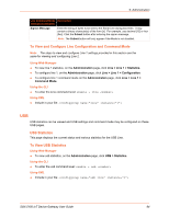
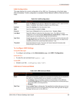
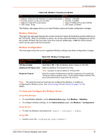
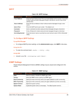
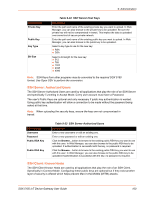
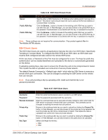
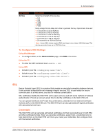
9: Administration Table 9-28 Modbus Transmission Modes RTU ASCII Address: 8 bits (0 to 247 decimal, 0 is used for broadcast) Address: 2 CHARS Function: 8 bits (1 to 255, 0 is not valid) Function: 2 CHARS Data: N X 8 bits (N=0 to 252 bytes) Data: N CHARS (N=0 to 252 CHARS) CRC Check: 16 bits LRC Check: 2 CHARS The Modbus web pages allow you to check Modbus status and make configuration changes. Modbus Statistics This read-only web page displays the current connection status of the Modbus servers listening on the TCP ports. When a connection is active, the remote client information is displayed as well as the number of PDUs that have been sent and received. Additionally, a Kill link will be present which can be used to kill the connection. Modbus Configuration This web page shows the current negotiated Modbus settings and allows configuration changes. Table 9-29 Modbus Configuration Modbus Configuration Settings TCP Server State Additional TCP Server Port Response Timeout Description Select On or Off. If On, the Modbus server is active on TCP 502. Enter the Additional TCP Server Port, if any. Note: If present, is used in addition to TCP port 502. Enter the number of milliseconds to wait for a response on the serial side. The device returns exception code 11 to the network master controller if the slave serial device fails to reply within this time out. Note: The serial line protocol must also be configured for Modbus, in addition to configuring the Modbus server. See Line (on page 92) and Tunnel (on page 111) for details. To View and Configure the Modbus Server Using Web Manager To view Modbus statistics, on the Administration page, click Modbus > Statistics. To configure Modbus settings, on the Administration page, click Modbus > Configuration. Using the CLI To enter the Modbus command level: enable > configure > modbus Using XML Include in your file: SGX 5150 IoT Device Gateway User Guide 97
-
 1
1 -
2
-
3
-
4
-
5
-
6
-
7
-
8
-
9
-
10
-
11
-
12
-
13
-
14
-
15
-
16
-
17
-
18
-
19
-
20
-
21
-
22
-
23
-
24
-
25
-
26
-
27
-
28
-
29
-
30
-
31
-
32
-
33
-
34
-
35
-
36
-
37
-
38
-
39
-
40
-
41
-
42
-
43
-
44
-
45
-
46
-
47
-
48
-
49
-
50
-
51
-
52
-
53
-
54
-
55
-
56
-
57
-
58
-
59
-
60
-
61
-
62
-
63
-
64
-
65
-
66
-
67
-
68
-
69
-
70
-
71
-
72
-
73
-
74
-
75
-
76
-
77
-
78
-
79
-
80
-
81
-
82
-
83
-
84
-
85
-
86
-
87
-
88
-
89
-
90
-
91
-
 92
92 -
 93
93 -
 94
94 -
 95
95 -
 96
96 -
 97
97 -
 98
98 -
 99
99 -
 100
100 -
 101
101 -
 102
102 -
103
-
104
-
105
-
106
-
107
-
108
-
109
-
110
-
111
-
112
-
113
-
114
-
115
-
116
-
117
-
118
-
119
-
120
-
121
-
122
-
123
-
124
-
125
-
126
-
127
-
128
-
129
 |
 |
