Lantronix SGX 5150 User Guide - Page 27
Reset Button, To Start WPS, Installing the SGX 5150
 |
View all Lantronix SGX 5150 manuals
Add to My Manuals
Save this manual to your list of manuals |
Page 27 highlights
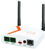
3: Installation of the SGX 5150 Table 3-13 WPS Status Indicator The WLAN link LED is used to indicate WPS status. See below for blink patterns. WPS Status WPS is enabled and on WPS has a profile error WPS has a timeout error Blink Pattern Short, continuous Long, long, long, short, short, 2 seconds off, continuous Long, long, long, short, short, short, short, 2 seconds off, continuous Notes: For Table 3-11 above, a "long" blink is 0.7 seconds of light followed by 0.3 seconds of no light. A "short" blink is a light that is on for only 0.2 seconds and followed by 0.2 seconds of no light. The diagnostic blink patterns reflect the highest priority fault condition. Also, the Diagnostic LED will give an initial, identifying blink pattern to indicate the type of diagnostic information it will display. All power and other non-network related diagnostic patterns begin with one long blink. All wired LAN related diagnostics patterns begin with two long blinks. All WLAN-related diagnostics patterns begin with three long blinks. Reset Button Press the Reset button as shown in Figure 3-1 for 6 seconds to reset the SGX 5150 configuration parameters to factory defaults and reboot. To Start WPS Using the Device 1. Place the end of a paper clip or similar object into the WPS opening (see Figure 3-12) and press and hold down for a minimum of 5 seconds. 2. Remove the paper clip to release the button. The unit will start Wi-Fi protected setup. Installing the SGX 5150 Be sure to place or mount the device securely on a flat horizontal or vertical surface. The device comes with brackets for mounting it, for example, on a wall. If using AC power, do not use outlets controlled by a wall switch. Observe the following guidelines when connecting the serial devices: The SGX 5150 serial ports support RS-232 or multi-protocol RS232/422/485 serial ports. Use a null modem cable to connect the serial port to another DTE device. Use a straight- though (modem) cable to connect the serial port to a DCE device. Connect your RJ-45 Ethernet cable to the RJ-45 port of the unit. Perform the following steps to install your device: 1. Attach the two antennas to the device. 2. Connect the equipment to the numbered device port (Serial 1/Serial 2) using appropriate cables and adapters. SGX 5150 IoT Device Gateway User Guide 27
-
 1
1 -
2
-
3
-
4
-
5
-
6
-
7
-
8
-
9
-
10
-
11
-
12
-
13
-
14
-
15
-
16
-
17
-
18
-
19
-
20
-
21
-
 22
22 -
 23
23 -
 24
24 -
 25
25 -
 26
26 -
 27
27 -
 28
28 -
 29
29 -
 30
30 -
 31
31 -
 32
32 -
33
-
34
-
35
-
36
-
37
-
38
-
39
-
40
-
41
-
42
-
43
-
44
-
45
-
46
-
47
-
48
-
49
-
50
-
51
-
52
-
53
-
54
-
55
-
56
-
57
-
58
-
59
-
60
-
61
-
62
-
63
-
64
-
65
-
66
-
67
-
68
-
69
-
70
-
71
-
72
-
73
-
74
-
75
-
76
-
77
-
78
-
79
-
80
-
81
-
82
-
83
-
84
-
85
-
86
-
87
-
88
-
89
-
90
-
91
-
92
-
93
-
94
-
95
-
96
-
97
-
98
-
99
-
100
-
101
-
102
-
103
-
104
-
105
-
106
-
107
-
108
-
109
-
110
-
111
-
112
-
113
-
114
-
115
-
116
-
117
-
118
-
119
-
120
-
121
-
122
-
123
-
124
-
125
-
126
-
127
-
128
-
129
 |
 |
