Lexmark M410 Service Manual - Page 50
Hardware Test Mode. Observe the, Fuser Lamp
 |
UPC - 734646261005
View all Lexmark M410 manuals
Add to My Manuals
Save this manual to your list of manuals |
Page 50 highlights
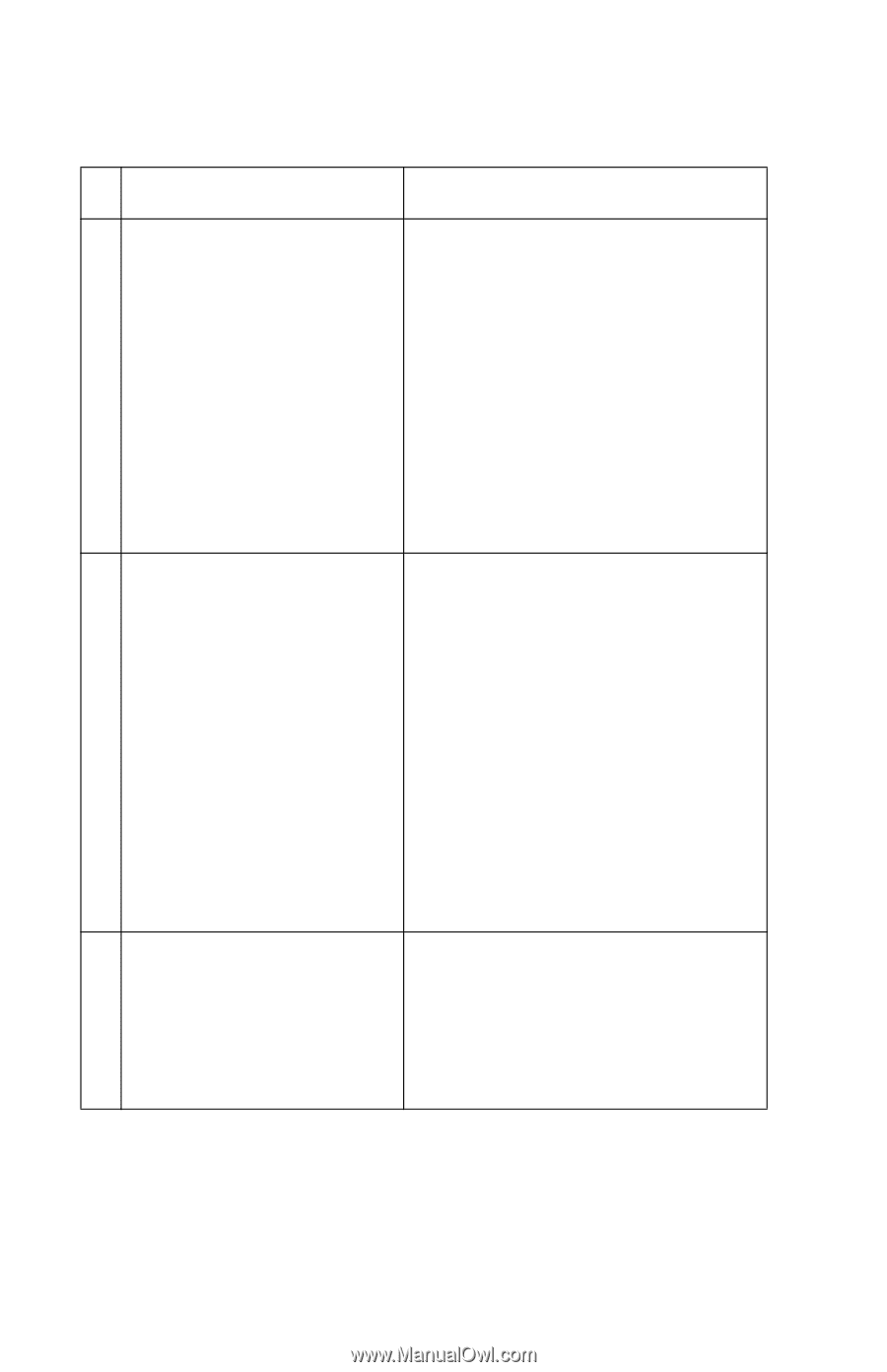
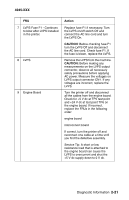
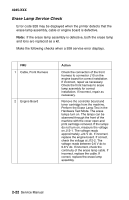
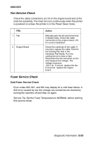
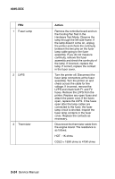
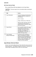
4045-XXX FRU 1 Fuser Lamp 2 LVPS 3 Thermistor Action Remove the controller board and run the Cooling Fan Test in the Hardware Test Mode. Observe the lamp through the left side frame. If the lamp doesn't come on, unplug the printer and check the continuity between the two pins on the fuser lamp cable going to the fuser assembly. If you do not measure continuity, remove the fuser assembly and check the continuity of the lamp. If incorrect, replace the lamp. If correct, replace the contact in the fuser cover. Turn the printer off. Disconnect the fuser lamp connectors at the fuser assembly. Turn the printer on and check across the cable for line voltage. If incorrect, remove the LVPS and check both F1 and F2 fuses. Remove the LVPS from the printer. Replace any open fuses and attach the power cord. If the fuses open, replace the LVPS. If the fuses open after the lamp cables are connected to the fuser, the fuser lamp circuit is shorted. Inspect the fuser lamp contacts in the fuser cover. Replace the contacts as necessary. Disconnect the thermistor cable from the engine board. The resistance is as follows: HOT - 1K ohms COLD = 150K ohms to 475K ohms 2-24 Service Manual
-
 1
1 -
2
-
3
-
4
-
5
-
6
-
7
-
8
-
9
-
10
-
11
-
12
-
13
-
14
-
15
-
16
-
17
-
18
-
19
-
20
-
21
-
22
-
23
-
24
-
25
-
26
-
27
-
28
-
29
-
30
-
31
-
32
-
33
-
34
-
35
-
36
-
37
-
38
-
39
-
40
-
41
-
42
-
43
-
44
-
 45
45 -
 46
46 -
 47
47 -
 48
48 -
 49
49 -
 50
50 -
 51
51 -
 52
52 -
 53
53 -
 54
54 -
 55
55 -
56
-
57
-
58
-
59
-
60
-
61
-
62
-
63
-
64
-
65
-
66
-
67
-
68
-
69
-
70
-
71
-
72
-
73
-
74
-
75
-
76
-
77
-
78
-
79
-
80
-
81
-
82
-
83
-
84
-
85
-
86
-
87
-
88
-
89
-
90
-
91
-
92
-
93
-
94
-
95
-
96
-
97
-
98
-
99
-
100
-
101
-
102
-
103
-
104
-
105
-
106
-
107
-
108
-
109
-
110
-
111
-
112
-
113
-
114
-
115
-
116
-
117
-
118
-
119
-
120
-
121
-
122
-
123
-
124
-
125
-
126
-
127
-
128
-
129
-
130
-
131
-
132
-
133
-
134
-
135
-
136
-
137
-
138
-
139
-
140
-
141
-
142
-
143
-
144
-
145
-
146
-
147
-
148
-
149
-
150
-
151
-
152
-
153
-
154
-
155
-
156
-
157
-
158
-
159
-
160
-
161
-
162
-
163
-
164
-
165
-
166
-
167
-
168
-
169
-
170
-
171
-
172
-
173
-
174
-
175
-
176
-
177
-
178
-
179
-
180
-
181
-
182
-
183
-
184
-
185
-
186
-
187
-
188
-
189
-
190
-
191
-
192
-
193
-
194
-
195
 |
 |