Lexmark M410 Service Manual - Page 57
Operator Panel Display Service Check
 |
UPC - 734646261005
View all Lexmark M410 manuals
Add to My Manuals
Save this manual to your list of manuals |
Page 57 highlights
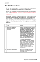
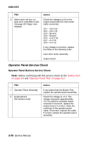
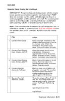
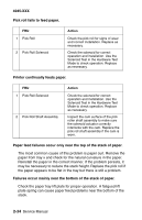
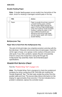
4045-XXX Operator Panel Display Service Check SERVICE TIP: The printer has detected a problem with the engine board, operator panel cable or operator panel assembly if POST does not complete and the printer emits 5 beeps and stops in a continuous pattern until the printer is turned off. The operator panel cable is an individual cable on some printers and a combination cable assembly with the cover switch cable on later models. Note: If the operator panel is operating properly except for a PEL or a few PELS missing or broken, run the "LCD Test" on page 3-8 from the hardware tests before continuing with this diagnostic service check. FRU 1 Operator Panel Cable 2 Operator Panel Display blank, 5 beeps, LED Off 3 Operator Panel Display blank, 5 beeps, LED On 4 Operator Panel all diamonds, No Beeps 5 Operator Panel all diamonds, 5 Beeps Action Check for proper installation of the cable at the engine board (J1) and at the operator panel. Check the continuity of the operator panel cable. If incorrect, replace the cable. Check the voltage at J1-2 on the engine board. It measures approximately +5 V dc. If incorrect, replace the engine board. If correct, replace the operator panel assembly. Check for ground between J1-4 and ground. If correct, replace the operator panel assembly. If incorrect, replace the engine board. Check to make sure a DIMM is not plugged in backward. This condition causes the printer to fail POST displaying all diamonds on the operator panel with no beeps. Check the voltage at Pins J1-1, J1-3 and J1-5. The voltage measures approximately +5 V dc. If incorrect, replace the FRUs in the following order: operator panel assembly engine board Diagnostic Information 2-31
-
 1
1 -
2
-
3
-
4
-
5
-
6
-
7
-
8
-
9
-
10
-
11
-
12
-
13
-
14
-
15
-
16
-
17
-
18
-
19
-
20
-
21
-
22
-
23
-
24
-
25
-
26
-
27
-
28
-
29
-
30
-
31
-
32
-
33
-
34
-
35
-
36
-
37
-
38
-
39
-
40
-
41
-
42
-
43
-
44
-
45
-
46
-
47
-
48
-
49
-
50
-
51
-
 52
52 -
 53
53 -
 54
54 -
 55
55 -
 56
56 -
 57
57 -
 58
58 -
 59
59 -
 60
60 -
 61
61 -
 62
62 -
63
-
64
-
65
-
66
-
67
-
68
-
69
-
70
-
71
-
72
-
73
-
74
-
75
-
76
-
77
-
78
-
79
-
80
-
81
-
82
-
83
-
84
-
85
-
86
-
87
-
88
-
89
-
90
-
91
-
92
-
93
-
94
-
95
-
96
-
97
-
98
-
99
-
100
-
101
-
102
-
103
-
104
-
105
-
106
-
107
-
108
-
109
-
110
-
111
-
112
-
113
-
114
-
115
-
116
-
117
-
118
-
119
-
120
-
121
-
122
-
123
-
124
-
125
-
126
-
127
-
128
-
129
-
130
-
131
-
132
-
133
-
134
-
135
-
136
-
137
-
138
-
139
-
140
-
141
-
142
-
143
-
144
-
145
-
146
-
147
-
148
-
149
-
150
-
151
-
152
-
153
-
154
-
155
-
156
-
157
-
158
-
159
-
160
-
161
-
162
-
163
-
164
-
165
-
166
-
167
-
168
-
169
-
170
-
171
-
172
-
173
-
174
-
175
-
176
-
177
-
178
-
179
-
180
-
181
-
182
-
183
-
184
-
185
-
186
-
187
-
188
-
189
-
190
-
191
-
192
-
193
-
194
-
195
 |
 |
