Samsung SRP-275CEPG Operation Manual - Page 17
Starting the Memory Switch setup mode, Function, Selectable value
 |
View all Samsung SRP-275CEPG manuals
Add to My Manuals
Save this manual to your list of manuals |
Page 17 highlights
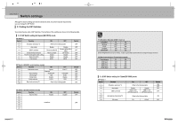
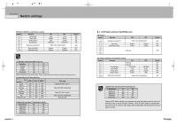
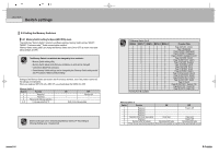
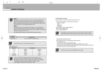
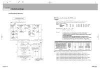
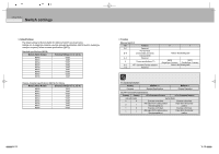
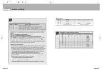
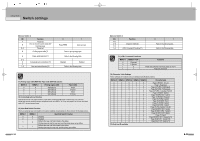
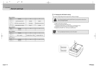
CHAPTER 3 Switch settings MSW 8-5 : When Off is selected, a bit of the "paper end sensor" in each status that is transmitted from the printer is changed every time the rear cover is open or closed. When On is selected, a bit of the "rear cover open / close" in each status that is transmitted from the printer is changed every time the rear cover is open or closed. When you replace a SRP270 with a SRP-275, you should adjust the MSW 8-5 to Off. MSW 8-8 : When Off is selected, a bit of the "automatic recoverable error" in each status that is transmitted from the printer is changed every time the rear cover is open. When On is selected, a bit of the "mechanical error" in each status that is transmitted from the printer is changed every time the rear cover is open. The setting of MSW 8-5 and 8-8 can be set by "Memory Switch setup mode". Customize value Function Paper roll width Selectable value 57.5 mm / 69.5 mm / 76 mm (default value) These setting can be set by "Memory Switch setup mode." Serial communication Function Baud rate Parity Handshake Data length 2400 bps 9600 bps None Even DSR/DTR 7 bits Selectable value 4800 bps 19200 bps Odd - XON/XOFF 8 bits There are two methods, DIP Switch and Memory Switch, to adjust the serial communication conditions. DIP Switch1-5 selects which is effective, DIP Switch or Memory Switch. To enable the "Serial communication" setting, you have to adjust the "Serial interface selection" function of DIP Switch 1-5 to "Memory Switch". These settings can be set by "Memory Switch setup mode". 3-8 Memory Switch setup mode The following items are specified in the Memory Switch setup mode: Basic Serial communication condition (Serial communication) - Transmission speed - Parity - Handshaking - Data length Receive buffer full release condition (MSW 8-7) Paper roll width (Customize value) Cover open status (MSW 8-5) All new settings will be lost if the power supply is turned off in the memory switch setup mode. Be sure to follow the proper procedure, and turn the power off at the correct time. Starting the Memory Switch setup mode Use the following procedure to start the Memory Switch setup mode. 1) Open the rear cover. 2) Turn the power on while pressing the FEED button. 3) Press the FEED button twice after POWER, ERROR, and PAPER OUT LEDs are lit. 4) Close rear the cover. The printer prints the enabled settings of the memory switches and instructions. 5) Follow the instructions to process the switch setup. In the Memory Switch setup, the POWER LED may be flashing. 3-9
-
 1
1 -
2
-
3
-
4
-
5
-
6
-
7
-
8
-
9
-
10
-
11
-
 12
12 -
 13
13 -
 14
14 -
 15
15 -
 16
16 -
 17
17 -
 18
18 -
 19
19 -
 20
20 -
 21
21 -
 22
22 -
23
-
24
-
25
-
26
-
27
-
28
-
29
-
30
-
31
-
32
-
33
-
34
-
35
-
36
-
37
-
38
-
39
-
40
-
41
-
42
-
43
-
44
-
45
-
46
-
47
-
48
-
49
-
50
-
51
-
52
-
53
-
54
-
55
-
56
-
57
-
58
-
59
-
60
-
61
-
62
-
63
-
64
-
65
-
66
-
67
-
68
-
69
-
70
-
71
-
72
-
73
-
74
-
75
-
76
-
77
-
78
-
79
-
80
-
81
-
82
-
83
-
84
-
85
-
86
-
87
-
88
-
89
-
90
-
91
-
92
-
93
-
94
-
95
-
96
-
97
-
98
-
99
-
100
-
101
-
102
-
103
-
104
-
105
-
106
-
107
-
108
-
109
-
110
 |
 |