SanDisk SDSDH-1024 Product Manual - Page 13
SPI Mode
 |
UPC - 710348911073
View all SanDisk SDSDH-1024 manuals
Add to My Manuals
Save this manual to your list of manuals |
Page 13 highlights
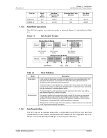
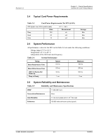
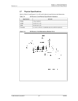
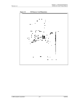
Revision 2.2 Chapter 1 - Introduction SanDisk SD Card Product Manual 1.12.8 Data Protection in the Flash Card Every sector is protected with an error correction code (ECC). The ECC is generated (in the memory card) when the sectors are written and validated when the data is read. If defects are found, the data is corrected prior to transmission to the host. 1.12.9 Write Protection Two-card level write-protection options are available: permanent and temporary. Both can be set using the PROGRAM_CSD command (refer to CSD Programming). The permanent write-protect bit, once set, cannot be cleared. This feature is implemented in the SD Card controller firmware and not with a physical OTP cell. Use the Write Protect (WP) Switch located on the card's side edge to prevent the host from writing to or erasing data on the card. The WP switch does not have any influence on the internal Permanent or Temporary WP bits in the CSD Register. 1.12.10 Copy Bit The copy bit can be used to mark an SD Card content as an original or a copy. The copy bit of the card is programmed as a copy when testing and formatting are performed during manufacturing. When set, the copy bit in the CSD Register is a copy and cannot be cleared. The card is available with the copy-bit set or cleared. If the bit is set, it indicates that the card is a master. This feature is implemented in the card's controller firmware and not with a physical OTP cell. 1.12.11 CSD Register All SD Card configuration information is stored in the CSD Register. The MSB bytes of the register contain manufacturer data and the two least significant bytes contain the hostcontrolled data: the card copy/write protection, and the user file format. The host can read the CSD Register and alter the host-controlled data bytes using the SEND_CSD and PROGRAM_CSD commands. 1.13 SPI Mode The SPI mode is a secondary communication protocol for SD cards. This mode is a subset of the SD Protocol, designed to communicate with an SPI channel, commonly found in Motorola and other vendors' microcontrollers. Table 1-3 SPI Mode Function Negotiating Operating Conditions Card Acquisition and Identification Description The operating condition negotiation function of the SD Card bus is supported differently in SPI mode by using the READ_OCR (CMD58) command. The host works within the valid voltage range (2.7 to 3.6 v) of the card or put the card in inactive state by sending a GO_INACTIVE command to the card. The host must know the number of cards currently connected on the bus. Specific card selection is done via the CS signal (CD/DAT3). The internal pull-up resistor on the CD/DAT3 line may be used for card detection (insertion/removal). Additional practical card detection methods can be found in SD Physical Specification's Application Notes given by the SDA. © 2004 SanDisk Corporation 1-9 12/08/04
-
 1
1 -
2
-
3
-
4
-
5
-
6
-
7
-
 8
8 -
 9
9 -
 10
10 -
 11
11 -
 12
12 -
 13
13 -
 14
14 -
 15
15 -
 16
16 -
 17
17 -
 18
18 -
19
-
20
-
21
-
22
-
23
-
24
-
25
-
26
-
27
-
28
-
29
-
30
-
31
-
32
-
33
-
34
-
35
-
36
-
37
-
38
-
39
-
40
-
41
-
42
-
43
-
44
-
45
-
46
-
47
-
48
-
49
-
50
-
51
-
52
-
53
-
54
-
55
-
56
-
57
-
58
-
59
-
60
-
61
-
62
-
63
-
64
-
65
-
66
-
67
-
68
-
69
-
70
-
71
-
72
-
73
-
74
-
75
-
76
-
77
-
78
-
79
-
80
-
81
-
82
-
83
-
84
-
85
-
86
-
87
-
88
-
89
-
90
-
91
-
92
-
93
-
94
-
95
-
96
-
97
-
98
-
99
-
100
-
101
-
102
-
103
-
104
-
105
-
106
-
107
-
108
-
109
-
110
-
111
-
112
-
113
-
114
-
115
-
116
-
117
-
118
-
119
-
120
-
121
-
122
-
123
 |
 |