SanDisk SDSDH-1024 Product Manual - Page 25
SPI Bus Topology
 |
UPC - 710348911073
View all SanDisk SDSDH-1024 manuals
Add to My Manuals
Save this manual to your list of manuals |
Page 25 highlights
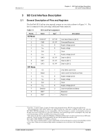
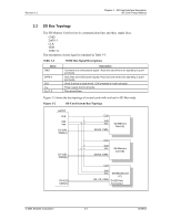
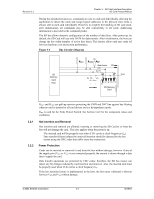
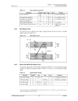
Revision 2.2 Chapter 3 - SD Card Interface Description SD Card Product Manual 3.3 SPI Bus Topology The SD Card SPI Interface is compatible with SPI hosts available on the market. Similar to any other SPI device, the SD Card SPI channel consists of the following four signals: • CS-Host-to-card Chip Select signal • CLK-Host-to-card Clock signal • DataIn-Host-to-card Data signal • DataOut-Card-to-host Data signal Another SPI common characteristic implemented in the SD Card are byte transfers. All data tokens are multiples of 8-bit bytes and always byte-aligned to the CS signal. The SPI standard defines the physical link only and not the complete data transfer protocol. In SPI bus mode, the SD Card uses a subset of the SD Card protocol and command set. The SD Card identification and addressing algorithms are replaced by the hardware CS signal. A card (slave) is selected for every command by asserting the CS signal (active low). Refer to Figure 3-2. The CS signal must be continuously active for the duration of the SPI transaction (command, response and data). The only exception is card-programming time. At this time the host can de-assert the CS signal without affecting the programming process. The bi-directional CMD and DAT lines are replaced by unidirectional dataIn and dataOut signals. This eliminates the ability to execute commands while data is being read or written which prevents sequential multi read/write operations. The Stop Transmission command can be sent during data read. In the multi block write operation a Stop Transmission token is sent as the first byte of the data block. Figure 3-4 SD Card Bus System Power Supply CS CS SPI Bus Master SPI Bus (CLK, DataIn, DataOut) SPI Card SPI Card © 2004 SanDisk Corporation 3-5 12/08/04
-
 1
1 -
2
-
3
-
4
-
5
-
6
-
7
-
8
-
9
-
10
-
11
-
12
-
13
-
14
-
15
-
16
-
17
-
18
-
19
-
 20
20 -
 21
21 -
 22
22 -
 23
23 -
 24
24 -
 25
25 -
 26
26 -
 27
27 -
 28
28 -
 29
29 -
 30
30 -
31
-
32
-
33
-
34
-
35
-
36
-
37
-
38
-
39
-
40
-
41
-
42
-
43
-
44
-
45
-
46
-
47
-
48
-
49
-
50
-
51
-
52
-
53
-
54
-
55
-
56
-
57
-
58
-
59
-
60
-
61
-
62
-
63
-
64
-
65
-
66
-
67
-
68
-
69
-
70
-
71
-
72
-
73
-
74
-
75
-
76
-
77
-
78
-
79
-
80
-
81
-
82
-
83
-
84
-
85
-
86
-
87
-
88
-
89
-
90
-
91
-
92
-
93
-
94
-
95
-
96
-
97
-
98
-
99
-
100
-
101
-
102
-
103
-
104
-
105
-
106
-
107
-
108
-
109
-
110
-
111
-
112
-
113
-
114
-
115
-
116
-
117
-
118
-
119
-
120
-
121
-
122
-
123
 |
 |
