SanDisk SDSDH-1024 Product Manual - Page 91
SPI Protocol
 |
UPC - 710348911073
View all SanDisk SDSDH-1024 manuals
Add to My Manuals
Save this manual to your list of manuals |
Page 91 highlights
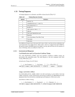
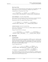
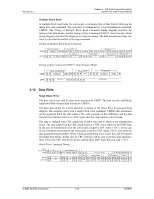
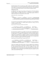
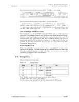
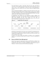
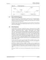
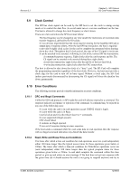
Revision 2.2 Chapter 5 - SPI Protocol SD Card Product Manual 5 SPI Protocol 5.1 SPI Bus Protocol Although the SanDisk SD Card channel is based on command and data bit-streams initiated by a start bit and terminated by a stop bit, the SPI channel is byte-oriented. Every command or data block is built of eight-bit bytes and byte aligned (multiples of eight clocks) to the CS signal. Similar to the SD Bus protocol, the SPI messages are built from command, response and data-block tokens. The host (master) controls all communication between host and cards. The host starts every bus transaction by asserting the CS signal, low. The response behavior in SPI Bus mode differs from the SD Bus mode in the following three ways: 1. The selected card always responds to the command. 2. An 8- or 16-bit response structure is used. 3. When the card encounters a data retrieval problem, it will respond with an error response (which replaces the expected data block) rather than time-out as in the SD Bus mode. In addition to the command response, every data block sent to the card during write operations will be responded with a special data response token. A data block may be as big as one card write block (WRITE_BL_LEN) and as small as a single byte. The default block length is specified in the CSD Register (512 bytes). A set block length of less than 512 bytes will cause a write error. The only valid write set block length is 512 bytes. CMD16 is not mandatory if the default is accepted. 5.2 Mode Selection The SD Card wakes up in the SD Bus mode. It will enter SPI mode if the CS signal is asserted (negative) during the reception of the reset command (CMD0). If the card recognizes that the SD Bus mode is required it will not respond to the command and remain in the SD Bus mode. If SPI mode is required, the card will switch to SPI mode and respond with the SPI mode R1 response. The only way to return to the SD Bus mode is by power cycling the card. In SPI mode, the SD Card protocol state machine is not observed. All the SD Memory Card commands supported in SPI mode are always available. The default command structure/protocol for SPI mode is that CRC checking is disabled. Since the card powers up in SD Bus mode, CMD0 must be followed by a valid CRC byte (even though the command is sent using the SPI structure). Once in SPI mode, CRCs are disabled by default. CMD0 is a static command and always generates the same 7-bit CRC of 4Ah. Adding the "1," end bit (bit 0) to the CRC creates a CRC byte of 95h. The following hexadecimal sequence can be used to send CMD0 in all situations for SPI mode, since the CRC byte (although required) is ignored once in SPI mode. The entire CMD0 sequence appears as 40 00 00 00 00 95 (hexadecimal). © 2004 SanDisk Corporation 5-1 12/08/04
-
 1
1 -
2
-
3
-
4
-
5
-
6
-
7
-
8
-
9
-
10
-
11
-
12
-
13
-
14
-
15
-
16
-
17
-
18
-
19
-
20
-
21
-
22
-
23
-
24
-
25
-
26
-
27
-
28
-
29
-
30
-
31
-
32
-
33
-
34
-
35
-
36
-
37
-
38
-
39
-
40
-
41
-
42
-
43
-
44
-
45
-
46
-
47
-
48
-
49
-
50
-
51
-
52
-
53
-
54
-
55
-
56
-
57
-
58
-
59
-
60
-
61
-
62
-
63
-
64
-
65
-
66
-
67
-
68
-
69
-
70
-
71
-
72
-
73
-
74
-
75
-
76
-
77
-
78
-
79
-
80
-
81
-
82
-
83
-
84
-
85
-
 86
86 -
 87
87 -
 88
88 -
 89
89 -
 90
90 -
 91
91 -
 92
92 -
 93
93 -
 94
94 -
 95
95 -
 96
96 -
97
-
98
-
99
-
100
-
101
-
102
-
103
-
104
-
105
-
106
-
107
-
108
-
109
-
110
-
111
-
112
-
113
-
114
-
115
-
116
-
117
-
118
-
119
-
120
-
121
-
122
-
123
 |
 |