SanDisk SDSDH-1024 Product Manual - Page 26
Electrical Interface
 |
UPC - 710348911073
View all SanDisk SDSDH-1024 manuals
Add to My Manuals
Save this manual to your list of manuals |
Page 26 highlights
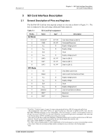
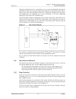
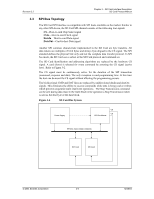
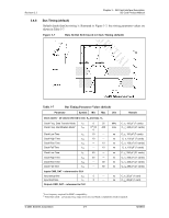
Revision 2.2 Chapter 3 - SD Card Interface Description SD Card Product Manual 3.3.1 Power Protection Same as in SD Card Bus Mode. 3.4 Electrical Interface The following sections provide valuable information about the electrical interface. 3.4.1 Power Up The power-up of the SD Card bus is handled locally, in each SD Card and in the bus master. Figure 3-5 Power-up Diagram Supply Voltage VDD max Bus master supply voltage VDD min Logic working level Valid voltage range for commands CMD0, 15, 55, and ACMD41 Valid voltage range for all other commands and memory access Power-up Supply Ramp-up Time Time time Timeout value for initialization process = 1 second Initialization Sequence ACMD NCC ACMD NCC 41 41 ACMD NCC 41 Initialization delay: the max. of 1 ms, 74 clock cycles and supply ramp- up time Optional repetitions of ACMD1 until no cards respond with busy bit set CMD2 After power up, including hot insertion (i.e., inserting a card when the bus is operating) the SD Card enters the idle state. During this state the SD Card ignores all bus transactions until ACMD41 is received (ACMD command type shall always precede with CMD55). ACMD41 is a special synchronization command used to negotiate the operation voltage range and to poll the cards until they are out of their power-up sequence. Besides the operation voltage profile of the cards, the response to ACMD41 contains a busy flag, indicating that the card is still working on its power-up procedure and is not ready for identification. This bit informs the host that the card is not ready. The host has to wait (and continue to poll the cards, each one on his turn) until this bit is cleared. The maximum period of power up procedure of single card shall not exceed one second. Getting individual cards, and the entire SD Card system, out of idle state is up to the responsibility of the bus master. Since the power up time and the supply ramp up time depend on application parameters such as the maximum number of SD Card s, the bus length and the power supply unit, the host must ensure that the power is built up to the operating level (the same level which will be specified in ACMD41) before ACMD41 is transmitted. © 2004 SanDisk Corporation 3-6 12/08/04
-
 1
1 -
2
-
3
-
4
-
5
-
6
-
7
-
8
-
9
-
10
-
11
-
12
-
13
-
14
-
15
-
16
-
17
-
18
-
19
-
20
-
 21
21 -
 22
22 -
 23
23 -
 24
24 -
 25
25 -
 26
26 -
 27
27 -
 28
28 -
 29
29 -
 30
30 -
 31
31 -
32
-
33
-
34
-
35
-
36
-
37
-
38
-
39
-
40
-
41
-
42
-
43
-
44
-
45
-
46
-
47
-
48
-
49
-
50
-
51
-
52
-
53
-
54
-
55
-
56
-
57
-
58
-
59
-
60
-
61
-
62
-
63
-
64
-
65
-
66
-
67
-
68
-
69
-
70
-
71
-
72
-
73
-
74
-
75
-
76
-
77
-
78
-
79
-
80
-
81
-
82
-
83
-
84
-
85
-
86
-
87
-
88
-
89
-
90
-
91
-
92
-
93
-
94
-
95
-
96
-
97
-
98
-
99
-
100
-
101
-
102
-
103
-
104
-
105
-
106
-
107
-
108
-
109
-
110
-
111
-
112
-
113
-
114
-
115
-
116
-
117
-
118
-
119
-
120
-
121
-
122
-
123
 |
 |
