SanDisk SDSDH-1024 Product Manual - Page 35
CSD_STRUCTURE, Table 3-12, CSD Register Structure, Table 3-13, TAAC Access Time Definition,
 |
UPC - 710348911073
View all SanDisk SDSDH-1024 manuals
Add to My Manuals
Save this manual to your list of manuals |
Page 35 highlights
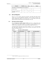
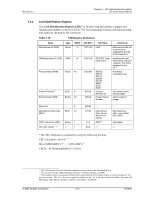
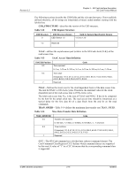
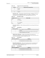
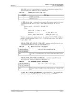
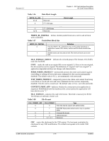
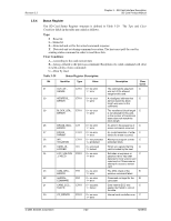
Revision 2.2 Chapter 3 - SD Card Interface Description SD Card Product Manual The following sections describe the CSD fields and the relevant data types. If not explicitly defined otherwise, all bit strings are interpreted as binary coded numbers starting with the left bit first. • CSD_STRUCTURE-describes the version of the CSD structure. Table 3-12 CSD Register Structure CSD Structure 0 CSD Structure Version CSD Version 1.0 Valid for System Specification Version v1.0 to v1.10 1-3 Reserved --- • TAAC-defines the asynchronous part (relative to the SD Card clock (CLK)) of the read access time. Table 3-13 TAAC Access Time Definition TAAC Bit Position 2:0 Code Time exponent 0=1 ns, 1=10 ns, 2=100 ns, 3=1 us, 4=10 us, 5=100 us, 6=1 ms, 7=10 ms 6:3 Time value 0=reserved, 1=1.0, 2=1.2, 3=1.3, 4=1.5, 5=2.0, 6=2.5, 7=3.0, 8=3.5, 9=4.0, A=4.5, B=5.0, C=5.5, D=6.0, E=7.0, F=8.0 7 Reserved • NSAC-Defines the worst case for the clock dependent factor of the data access time. The unit for NSAC is 100 clock cycles. Therefore, the maximal value for the clock dependent part of the read access time is 25.5k clock cycles. The total read access time NAC is the sum of TAAC and NSAC. It has to be computed by the host for the actual clock rate. The read access time should be interpreted as a typical delay for the first data bit of a data block from the end bit on the read commands. • TRAN_SPEED-Table 3-14 defines the maximum data transfer rate TRAN_SPEED. Table 3-14 Max. Data Transfer Rate Definition TRAN_SPEED Bit 2:0 6:3 7 Transfer rate exponent Code 0=100 kb/s, 1=1 Mb/s, 2=10 Mb/s, 3=100 Mb/s, 4...7=reserved Time mantissa 0=reserved, 1=1.0, 2=1.2, 3=1.3, 4=1.5, 5=2.0, 6=2.5, 7=3.0, 8=3.5, 9=4.0, A=4.5, B=5.0, C=5.5, D=6.0, E=7.0, F=8.0 Reserved • CCC-The SD Card command set is divided into subsets (command classes). The Card Command Class Register (CCC) defines which command classes are supported by this card. A value of "1" in a CCC bit means that the corresponding command class is supported. © 2004 SanDisk Corporation 3-15 12/08/04
-
 1
1 -
2
-
3
-
4
-
5
-
6
-
7
-
8
-
9
-
10
-
11
-
12
-
13
-
14
-
15
-
16
-
17
-
18
-
19
-
20
-
21
-
22
-
23
-
24
-
25
-
26
-
27
-
28
-
29
-
 30
30 -
 31
31 -
 32
32 -
 33
33 -
 34
34 -
 35
35 -
 36
36 -
 37
37 -
 38
38 -
 39
39 -
 40
40 -
41
-
42
-
43
-
44
-
45
-
46
-
47
-
48
-
49
-
50
-
51
-
52
-
53
-
54
-
55
-
56
-
57
-
58
-
59
-
60
-
61
-
62
-
63
-
64
-
65
-
66
-
67
-
68
-
69
-
70
-
71
-
72
-
73
-
74
-
75
-
76
-
77
-
78
-
79
-
80
-
81
-
82
-
83
-
84
-
85
-
86
-
87
-
88
-
89
-
90
-
91
-
92
-
93
-
94
-
95
-
96
-
97
-
98
-
99
-
100
-
101
-
102
-
103
-
104
-
105
-
106
-
107
-
108
-
109
-
110
-
111
-
112
-
113
-
114
-
115
-
116
-
117
-
118
-
119
-
120
-
121
-
122
-
123
 |
 |
