SanDisk SDSDH-1024 Product Manual - Page 89
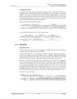
Multiple Block Write
 |
UPC - 710348911073
View all SanDisk SDSDH-1024 manuals
Add to My Manuals
Save this manual to your list of manuals |
Page 89 highlights
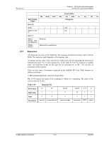
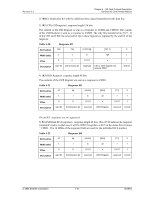
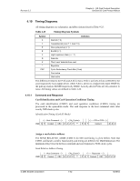
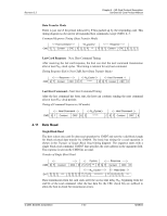
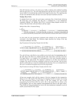
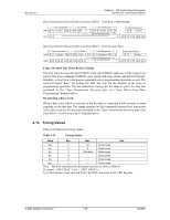
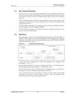
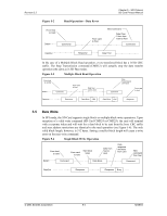
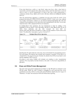
Revision 2.2 Chapter 4 - SD Card Protocol Description SanDisk SD Card Product Manual If the SD Card does not have a free data receive buffer, it indicates this condition by pulling down the data line to low. The card stops pulling down the data line as soon as at least one receive buffer for the defined data transfer block length becomes free. This signaling does not give any information about the data write status that must be polled by the host. Multiple Block Write In multiple block write mode, the card expects continuous flow of data blocks following the initial host write command. The data flow is terminated by a stop transmission command (CMD12). The Multiple Block Write Command timing diagram describes the timing of the data blocks with and without card busy signal. Multiple Block Write Command Timing Card Response CMD E Z Z P PPPPP P P PPP P P P P NWR Write Data CRC Status NWR Write Data CRC Status Busy NW R DAT Z Z P*P S Data+CRC E Z Z S Status E Z P*P S Data+CRC E Z Z S Status E S L*L E Z P*P In write mode, the stop transmission command works similarly to the stop transmission command in the Read Mode. The following figure describes the timing of the stop command in different card states. Stop Transmission During Data Transfer from the Host Host Command NCRCycles Card Response CMD S T Content CRC E Z Z P P* ****P S T Content CRC E Card is Programming DAT D D D D D D D D D D E Z Z S L ********* Host Command ST Content EZZZZZZZZ The card will treat a data block as successfully received and ready for programming only if the CRC data of the block was validated and the CRC status token sent back to the host. The figure below is an example of an interrupted (by a host stop command) attempt to transmit the CRC status block. The sequence is identical to all other stop transmission examples. The end bit of the host command is followed, on the data line, with one more data bit, end bit and two Z clock for switching the bus direction. The received data block in this case is considered incomplete and will not be programmed. Stop Transmission during CRC Status Transfer from the Card Host Command NCRCycles Card Response CMD S T Content CRC E Z Z P P* ****P S T Content CRC E Data Block CRC Status Card is Programming DAT D D D D D Z Z S Status E Z Z S L ********* Host Command ST Content EZZZZZZZZ All previous examples dealt with the scenario of the host stopping the data transmission during an active data transfer. The following two diagrams describe a scenario of receiving the stop transmission between data blocks. In the first example, the card is busy programming the last block while the card is idle in the second block as shown in the second diagram. However, there remains un-programmed data blocks in the input buffers. These blocks are being programmed as soon as the stop transmission command is received and the card activates the busy signal. © 2004 SanDisk Corporation 4-45 12/08/04
-
 1
1 -
2
-
3
-
4
-
5
-
6
-
7
-
8
-
9
-
10
-
11
-
12
-
13
-
14
-
15
-
16
-
17
-
18
-
19
-
20
-
21
-
22
-
23
-
24
-
25
-
26
-
27
-
28
-
29
-
30
-
31
-
32
-
33
-
34
-
35
-
36
-
37
-
38
-
39
-
40
-
41
-
42
-
43
-
44
-
45
-
46
-
47
-
48
-
49
-
50
-
51
-
52
-
53
-
54
-
55
-
56
-
57
-
58
-
59
-
60
-
61
-
62
-
63
-
64
-
65
-
66
-
67
-
68
-
69
-
70
-
71
-
72
-
73
-
74
-
75
-
76
-
77
-
78
-
79
-
80
-
81
-
82
-
83
-
 84
84 -
 85
85 -
 86
86 -
 87
87 -
 88
88 -
 89
89 -
 90
90 -
 91
91 -
 92
92 -
 93
93 -
 94
94 -
95
-
96
-
97
-
98
-
99
-
100
-
101
-
102
-
103
-
104
-
105
-
106
-
107
-
108
-
109
-
110
-
111
-
112
-
113
-
114
-
115
-
116
-
117
-
118
-
119
-
120
-
121
-
122
-
123
 |
 |
