SanDisk SDSDH-1024 Product Manual - Page 31
SD Card Registers
 |
UPC - 710348911073
View all SanDisk SDSDH-1024 manuals
Add to My Manuals
Save this manual to your list of manuals |
Page 31 highlights
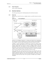
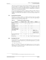
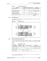
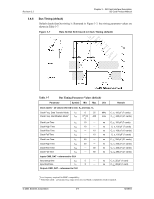
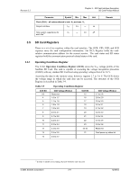
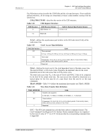
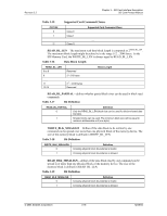
Revision 2.2 Chapter 3 - SD Card Interface Description SD Card Product Manual Parameter Symbol Min Max Unit Clock (CLK) - all values referred to min. VIH and max. VIL Output hold time tOH 2.5 --- ns Total system capacitance for each line11 CL --- 40 pF Remark 3.5 SD Card Registers There is a set of six registers within the card interface. The OCR, CID, CSD, and SCR registers carry the card configuration information. The RCA Register holds the cardrelative communication address for the current session. The card status and SD status registers hold the communication protocol related status of the card. 3.5.1 Operating Conditions Register The 32-bit Operation Conditions Register (OCR) stores the VDD voltage profile of the SanDisk SD Card. The card is capable of executing the voltage recognition procedure (CMD1) with any standard SD Card host using operating voltages from 2 to 3.6 V. Accessing the data in the memory array, however, requires 2.7 to 3.6 V. The OCR shows the voltage range in which the card data can be accessed. The structure of the OCR Register is described in Table 3-9. Table 3-9 Operating Conditions Register OCR Bit 0-3 4 5 6 7 8 9 10 11 VDD Voltage Window Reserved 1.6 to 1.7 1.7 to 1.8 1.8 to 1.9 1.9 to 2.0 2.0 to 2.1 2.1 to 2.2 2.2 to 2.3 2.3 to 2.4 OCR Bit 15 16 17 18 19 20 21 22 23 VDD Voltage Window 2.7 to 2.8 2.8 to 2.9 2.9 to 3.0 3.0 to 3.1 3.1 to 3.2 3.2 to 3.3 3.3 to 3.4 3.4 to 3.5 3.5 to 3.6 12 2.4 to 2.5 13 2.5 to 2.6 14 2.6 to 2.7 24-30 31 Reserved Card power-up status bit 11 In order to satisfy severe timing, the host will drive only one card. © 2004 SanDisk Corporation 3-11 12/08/04
-
 1
1 -
2
-
3
-
4
-
5
-
6
-
7
-
8
-
9
-
10
-
11
-
12
-
13
-
14
-
15
-
16
-
17
-
18
-
19
-
20
-
21
-
22
-
23
-
24
-
25
-
 26
26 -
 27
27 -
 28
28 -
 29
29 -
 30
30 -
 31
31 -
 32
32 -
 33
33 -
 34
34 -
 35
35 -
 36
36 -
37
-
38
-
39
-
40
-
41
-
42
-
43
-
44
-
45
-
46
-
47
-
48
-
49
-
50
-
51
-
52
-
53
-
54
-
55
-
56
-
57
-
58
-
59
-
60
-
61
-
62
-
63
-
64
-
65
-
66
-
67
-
68
-
69
-
70
-
71
-
72
-
73
-
74
-
75
-
76
-
77
-
78
-
79
-
80
-
81
-
82
-
83
-
84
-
85
-
86
-
87
-
88
-
89
-
90
-
91
-
92
-
93
-
94
-
95
-
96
-
97
-
98
-
99
-
100
-
101
-
102
-
103
-
104
-
105
-
106
-
107
-
108
-
109
-
110
-
111
-
112
-
113
-
114
-
115
-
116
-
117
-
118
-
119
-
120
-
121
-
122
-
123
 |
 |
