SanDisk SDSDH-1024 Product Manual - Page 51
Data Transfer Mode
 |
UPC - 710348911073
View all SanDisk SDSDH-1024 manuals
Add to My Manuals
Save this manual to your list of manuals |
Page 51 highlights
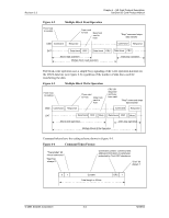
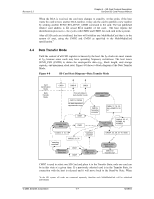
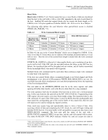
Revision 2.2 Chapter 4 - SD Card Protocol Description SanDisk SD Card Product Manual When the RCA is received, the card state changes to stand-by. At this point, if the host wants the card to have another RCA number, it may ask the card to publish a new number by sending another SEND_RELATIVE_ADDR command to the card. The last published relative card address is the actual RCA number of the card. The host repeats the identification process (i.e., the cycles with CMD2 and CMD3 for each card in the system). After all SD cards are initialized, the host will initialize any MultiMediaCard that is in the system (if any), using the CMD2 and CMD3 as specified in the MultiMediaCard specification.4 4.4 Data Transfer Mode Until the content of all CSD registers is known by the host, the fPP clock rate must remain at fOD because some cards may have operating frequency restrictions. The host issues SEND_CSD (CMD9) to obtain the card-specific data (e.g., block length, card storage capacity, and maximum clock rate). Figure 4-8 shows a block diagram of the Data Transfer Mode. Figure 4-8 SD Card State Diagram-Data Transfer Mode Card Identification Mode Data Transfer Mode CMD3 CMD15 CMD0 From all states in data-transfer mode CMD13, CMD55 No state transition in data-transfer mode Standby State (stby) CMD7 CMD7 Send-data State (data) CMD12, "operation complete" CMD6, 17, 18, 30, 56(r) ACMD13, 22, 51 Transfer State (trans) CMD16, 32...37, ACMD6, 42 ACMD23 CMD4, 9, 10, 3 CMD28, 29, 38 "operation complete" Disconnect State (dis) CMD7 CMD7 "operation complete" Programming State (prg) CMD24, 25, 26, 27, 42, 56(w) Receive-data State (rcv) CMD12 or "transfer end" CMD7 is used to select one SD Card and place it in the Transfer State; only one card can be in this state at a given time. If a previously selected card is in the Transfer State, its connection with the host is released and it will move back to the Stand-by State. When 4In the SD system, all cards are connected separately therefore each MultiMediaCard will be initialized individually. © 2004 SanDisk Corporation 4-7 12/08/04
-
 1
1 -
2
-
3
-
4
-
5
-
6
-
7
-
8
-
9
-
10
-
11
-
12
-
13
-
14
-
15
-
16
-
17
-
18
-
19
-
20
-
21
-
22
-
23
-
24
-
25
-
26
-
27
-
28
-
29
-
30
-
31
-
32
-
33
-
34
-
35
-
36
-
37
-
38
-
39
-
40
-
41
-
42
-
43
-
44
-
45
-
 46
46 -
 47
47 -
 48
48 -
 49
49 -
 50
50 -
 51
51 -
 52
52 -
 53
53 -
 54
54 -
 55
55 -
 56
56 -
57
-
58
-
59
-
60
-
61
-
62
-
63
-
64
-
65
-
66
-
67
-
68
-
69
-
70
-
71
-
72
-
73
-
74
-
75
-
76
-
77
-
78
-
79
-
80
-
81
-
82
-
83
-
84
-
85
-
86
-
87
-
88
-
89
-
90
-
91
-
92
-
93
-
94
-
95
-
96
-
97
-
98
-
99
-
100
-
101
-
102
-
103
-
104
-
105
-
106
-
107
-
108
-
109
-
110
-
111
-
112
-
113
-
114
-
115
-
116
-
117
-
118
-
119
-
120
-
121
-
122
-
123
 |
 |
