SanDisk SDSDH-1024 Product Manual - Page 24
Bus Circuitry Diagram
 |
UPC - 710348911073
View all SanDisk SDSDH-1024 manuals
Add to My Manuals
Save this manual to your list of manuals |
Page 24 highlights
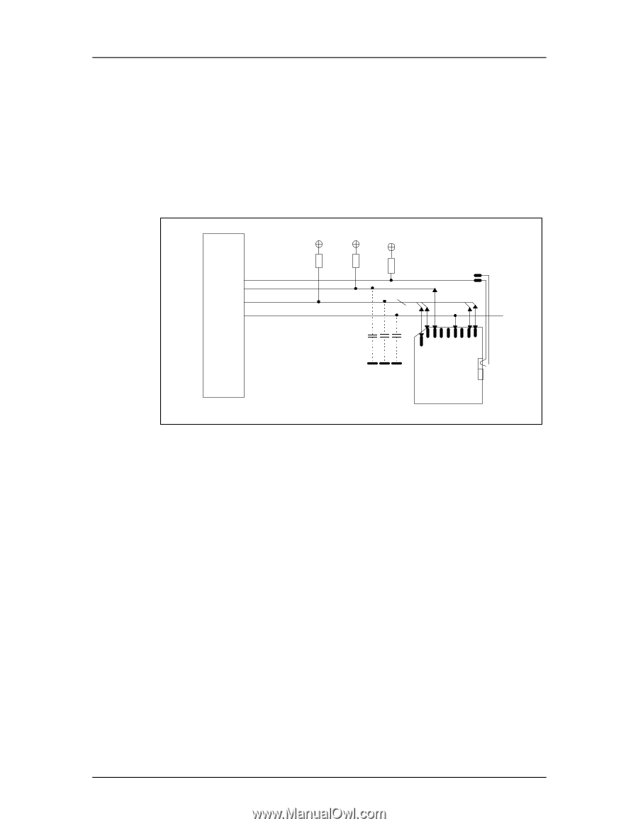
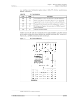
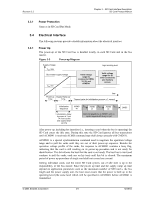
Revision 2.2 Chapter 3 - SD Card Interface Description SD Card Product Manual During the initialization process, commands are sent to each card individually, allowing the application to detect the cards and assign logical addresses to the physical slots. Data is always sent to each card individually. However, to simplify the handling of the card stack, after initialization, all commands may be sent concurrently to all cards. Addressing information is provided in the command packet. The SD bus allows dynamic configuration of the number of data lines. After power-up, by default, the SD Card will use only DAT0 for data transfer. After initialization, the host can change the bus width (number of active data lines). This feature allows and easy trade off between hardware cost and system performance. Figure 3-3 Bus Circuitry Diagram SD Memory Card Host RDAT RCMD RWP Write Protect Vss CMD DAT0-3 C1 C2 C3 1 2 3 4 5 6 7 8 9 SD Memory Card CLK 3.2.1 3.2.2 RDAT and RCMD are pull-up resistors protecting the CMD and DAT line against bus floating when no card is inserted or all card drivers are in a hi-impedance mode. RWP is used for the Write Protect Switch. See Section 5.4.2 for the component values and conditions. Hot Insertion and Removal Hot insertion and removal are allowed; inserting or removing the SD Card to or from the bus will not damage the card. This also applies when the power is up. • The inserted card will be properly reset when CLK carries a clock frequency (fpp). • Data transfer failures induced by removal/insertion should be detected by the bus master using the CRC codes that suffix every bus transaction. Power Protection Cards can be inserted or removed to and from the bus without damage, however if one of the supply pins (VDD or VSS) is not connected properly, the current is drawn through a data line to supply the card. Data transfer operations are protected by CRC codes; therefore, the SD bus master can detect any bit changes induced by card insertion and removal. Also, the inserted card must be properly reset when CLK carries a clock frequency fPP. If the hot insertion feature is implemented in the host, the host must withstand a shortcut between VDD and VSS without damage. © 2004 SanDisk Corporation 3-4 12/08/04
-
 1
1 -
2
-
3
-
4
-
5
-
6
-
7
-
8
-
9
-
10
-
11
-
12
-
13
-
14
-
15
-
16
-
17
-
18
-
 19
19 -
 20
20 -
 21
21 -
 22
22 -
 23
23 -
 24
24 -
 25
25 -
 26
26 -
 27
27 -
 28
28 -
 29
29 -
30
-
31
-
32
-
33
-
34
-
35
-
36
-
37
-
38
-
39
-
40
-
41
-
42
-
43
-
44
-
45
-
46
-
47
-
48
-
49
-
50
-
51
-
52
-
53
-
54
-
55
-
56
-
57
-
58
-
59
-
60
-
61
-
62
-
63
-
64
-
65
-
66
-
67
-
68
-
69
-
70
-
71
-
72
-
73
-
74
-
75
-
76
-
77
-
78
-
79
-
80
-
81
-
82
-
83
-
84
-
85
-
86
-
87
-
88
-
89
-
90
-
91
-
92
-
93
-
94
-
95
-
96
-
97
-
98
-
99
-
100
-
101
-
102
-
103
-
104
-
105
-
106
-
107
-
108
-
109
-
110
-
111
-
112
-
113
-
114
-
115
-
116
-
117
-
118
-
119
-
120
-
121
-
122
-
123
 |
 |