SanDisk SDSDH-1024 Product Manual - Page 56
Mechanical Write Protect Switch, Card's Internal Write Protection Optional, Table 4-3, Lock Card
 |
UPC - 710348911073
View all SanDisk SDSDH-1024 manuals
Add to My Manuals
Save this manual to your list of manuals |
Page 56 highlights
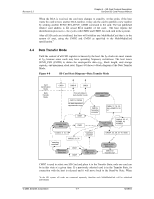
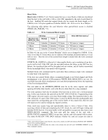
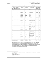
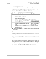
Revision 2.2 Chapter 4 - SD Card Protocol Description SanDisk SD Card Product Manual 4.4.7 Mechanical Write Protect Switch A mechanical sliding tablet on the side of the card (refer to the mechanical description), controlled by the user, indicates whether or not a given card is write-protected. If the sliding tablet is in the position of the window open, it means the card is write-protected. If the window is closed, the card is not write-protected. A proper, matched, switch on the socket side will indicate to the host that the card is writeprotected or not. It is the responsibility of the host to protect the card. The position of the write-protect switch is unknown to the internal circuitry of the card. Card's Internal Write Protection (Optional) Card data may be protected against either erase or write. The entire card may be permanently write-protected by the manufacturer or content provider by setting the permanent or temporary write protect bits in the CSD Register. Card Lock/Unlock Operation The password-protection feature enables the host to lock a card while providing a password that will be used later for unlocking the card. The password and its size are kept in 128-bit PWD and 8-bit PWD_LEN registers, respectively. These registers are non-volatile which protects a power cycle erase. Locked cards respond to (and execute) all commands in the "basic" command class (class 0), ACMD41, CMD16 and "lock card" command class. Thus the host is allowed to reset, initialize, select, query for status, etc., but not to access data on the card. If the password was previously set (the value of PWD_LEN is not '0'), it will be locked automatically after power on. Similar to the existing CSD Register write commands the lock/unlock command is available in "transfer state" only. This means that it does not include an address argument and the card has to be selected before using it. The card lock/unlock command has the structure and bus transaction type of a regular single block write command. The transferred data block includes all the required information of the command (password setting mode, PWD itself, card lock/unlock etc.). The following table describes the structure of the command data block. Table 4-3 Lock Card Data Structure Byte Bit Bit Bit Bit 76 5 4 0 Reserved 1 2 ... PWDS_LEN + 1 Bit 3 Bit 2 Bit 1 Bit 0 ERASE LOCK_UNLOCK CLR_PWD SET_PWD PWDS_LEN Password Data © 2004 SanDisk Corporation 4-12 12/08/04
-
 1
1 -
2
-
3
-
4
-
5
-
6
-
7
-
8
-
9
-
10
-
11
-
12
-
13
-
14
-
15
-
16
-
17
-
18
-
19
-
20
-
21
-
22
-
23
-
24
-
25
-
26
-
27
-
28
-
29
-
30
-
31
-
32
-
33
-
34
-
35
-
36
-
37
-
38
-
39
-
40
-
41
-
42
-
43
-
44
-
45
-
46
-
47
-
48
-
49
-
50
-
 51
51 -
 52
52 -
 53
53 -
 54
54 -
 55
55 -
 56
56 -
 57
57 -
 58
58 -
 59
59 -
 60
60 -
 61
61 -
62
-
63
-
64
-
65
-
66
-
67
-
68
-
69
-
70
-
71
-
72
-
73
-
74
-
75
-
76
-
77
-
78
-
79
-
80
-
81
-
82
-
83
-
84
-
85
-
86
-
87
-
88
-
89
-
90
-
91
-
92
-
93
-
94
-
95
-
96
-
97
-
98
-
99
-
100
-
101
-
102
-
103
-
104
-
105
-
106
-
107
-
108
-
109
-
110
-
111
-
112
-
113
-
114
-
115
-
116
-
117
-
118
-
119
-
120
-
121
-
122
-
123
 |
 |
