SanDisk SDSDH-1024 Product Manual - Page 87
Data Read
 |
UPC - 710348911073
View all SanDisk SDSDH-1024 manuals
Add to My Manuals
Save this manual to your list of manuals |
Page 87 highlights
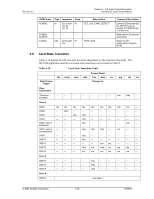
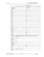
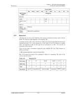
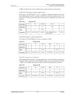
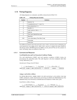
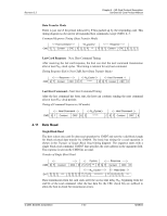
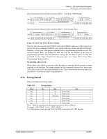
Revision 2.2 Chapter 4 - SD Card Protocol Description SanDisk SD Card Product Manual Data Transfer Mode There is just one Z bit period followed by P bits pushed up by the responding card. This timing diagram is relevant for all responded host commands except CMD1, 2, 3. Command Response Timing (Data Transfer Mode) Host Command NCRCycles CMD S T Content CRC E Z Z P *** Response P S T Content CRC Z E Z Z Z Last Card Response-Next Host Command Timing After receiving the last card response, the host can start the next command transmission after at least NRC clock cycles. This timing is relevant for any host command. Timing Response End to Next CMD Start (Data Transfer Mode) Response CMD S T Content CRC E Z NRCCycles ****** Host Command Z S T Content CRCZ E Last Host Command-Next Host Command Timing After the last command has been sent, the host can continue sending the next command after at least NCC clock periods. Timing of Command Sequences (All modes) Host Command CMD S T Content CRC E Z NCCCycles ****** Host Command Z S T Content CRCZ E 4.11 Data Read Single Block Read The host selects one card for data read operation by CMD7 and sets the valid block length for block-oriented data transfer by CMD16. The basic bus timing for a read operation is shown in the Transfer of Single Block Read timing diagram. The sequence starts with a single block read command, CMD17 that specifies the start address in the argument field. The response is sent on the CMD line as usual. Transfer of Single Block Read CMD S T Content Cycles Response CRC E Z Z P *** P S T Content CRC E DAT Z Z Z **** NAC Cycles Z Z Z Z Z Z P ********** Read Data P S D D D *** Data transmission from the card starts after the access time delay NAC beginning from the end bit of the read command. After the last data bit, the CRC check bits are suffixed to allow the host to check for transmission errors. © 2004 SanDisk Corporation 4-43 12/08/04
-
 1
1 -
2
-
3
-
4
-
5
-
6
-
7
-
8
-
9
-
10
-
11
-
12
-
13
-
14
-
15
-
16
-
17
-
18
-
19
-
20
-
21
-
22
-
23
-
24
-
25
-
26
-
27
-
28
-
29
-
30
-
31
-
32
-
33
-
34
-
35
-
36
-
37
-
38
-
39
-
40
-
41
-
42
-
43
-
44
-
45
-
46
-
47
-
48
-
49
-
50
-
51
-
52
-
53
-
54
-
55
-
56
-
57
-
58
-
59
-
60
-
61
-
62
-
63
-
64
-
65
-
66
-
67
-
68
-
69
-
70
-
71
-
72
-
73
-
74
-
75
-
76
-
77
-
78
-
79
-
80
-
81
-
 82
82 -
 83
83 -
 84
84 -
 85
85 -
 86
86 -
 87
87 -
 88
88 -
 89
89 -
 90
90 -
 91
91 -
 92
92 -
93
-
94
-
95
-
96
-
97
-
98
-
99
-
100
-
101
-
102
-
103
-
104
-
105
-
106
-
107
-
108
-
109
-
110
-
111
-
112
-
113
-
114
-
115
-
116
-
117
-
118
-
119
-
120
-
121
-
122
-
123
 |
 |
