SanDisk SDSDH-1024 Product Manual - Page 49
SD Memory Card State Diagram-Card Identification Mode
 |
UPC - 710348911073
View all SanDisk SDSDH-1024 manuals
Add to My Manuals
Save this manual to your list of manuals |
Page 49 highlights
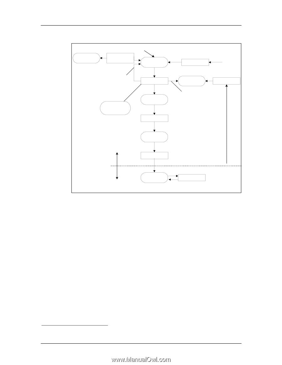
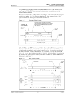
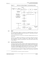
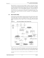
Revision 2.2 Chapter 4 - SD Card Protocol Description SanDisk SD Card Product Manual Figure 4-7 SD Memory Card State Diagram-Card Identification Mode SPI Operation Mode CMD0 CS Asserted (0) Power On Idle State (idle) Card is busy or host omitted voltage range ACMD41 CMD0 Inactive State (ina) From all states except "ina" CMD15 No response (non valid command) must be an MMC Start MMC initialization process starting at CMD1 Ready State (ready) Cards w/non-compatible voltage range CMD2 Identification State (ident) Card Identification Mode CMD3 Card responds w/new RCA Data Transfer Mode Standby State (stby) CMD3 Card responds w/new RCA From all states in Data Transfer Mode 4.3.1 Reset The GO_IDLE_STATE (CMD0) is the software-reset command that makes each SD Card move into an idle state regardless of the card's current state. Cards already in an inactive state are not affected by this command. After power-on by the host, all cards are in an idle state, including cards that were in an inactive state.1 After power-on or CMD0, all card CMD lines are in input mode, waiting for the start-bit of the next command. The cards are initialized with a default relative card address (RCA=0x0000) and a default driver-stage-register setting (lowest speed, highest driving current capability). 4.3.2 Operating Voltage Range Validation The physical specification standard, defined by the SDA, requires that all SD cards can use any operating voltage between VDD-min and VDD-max to establish communication with the host. However, during data transfer, minimum and maximum values for VDD are defined in the Operations Condition Register (OCR) and may not cover the entire range. Card hosts are expected to read the CSD Register and select proper VDD values or reject the card. An SD Card that stores the CID and CSD data in the payload memory can communicate this information under data-transfer VDD conditions only. In other words, if the host and 1 At least 74 clock cycles are required prior to starting bus communication. © 2004 SanDisk Corporation 4-5 12/08/04
-
 1
1 -
2
-
3
-
4
-
5
-
6
-
7
-
8
-
9
-
10
-
11
-
12
-
13
-
14
-
15
-
16
-
17
-
18
-
19
-
20
-
21
-
22
-
23
-
24
-
25
-
26
-
27
-
28
-
29
-
30
-
31
-
32
-
33
-
34
-
35
-
36
-
37
-
38
-
39
-
40
-
41
-
42
-
43
-
 44
44 -
 45
45 -
 46
46 -
 47
47 -
 48
48 -
 49
49 -
 50
50 -
 51
51 -
 52
52 -
 53
53 -
 54
54 -
55
-
56
-
57
-
58
-
59
-
60
-
61
-
62
-
63
-
64
-
65
-
66
-
67
-
68
-
69
-
70
-
71
-
72
-
73
-
74
-
75
-
76
-
77
-
78
-
79
-
80
-
81
-
82
-
83
-
84
-
85
-
86
-
87
-
88
-
89
-
90
-
91
-
92
-
93
-
94
-
95
-
96
-
97
-
98
-
99
-
100
-
101
-
102
-
103
-
104
-
105
-
106
-
107
-
108
-
109
-
110
-
111
-
112
-
113
-
114
-
115
-
116
-
117
-
118
-
119
-
120
-
121
-
122
-
123
 |
 |