SanDisk SDSDH-1024 Product Manual - Page 85
Table 4-20, Response R2, Table 4-21, Response R3, Table 4-22, Response R6
 |
UPC - 710348911073
View all SanDisk SDSDH-1024 manuals
Add to My Manuals
Save this manual to your list of manuals |
Page 85 highlights
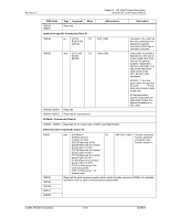
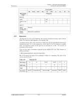
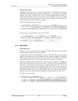
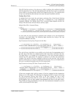
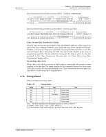
Revision 2.2 Chapter 4 - SD Card Protocol Description SanDisk SD Card Product Manual 2) R1b is identical to R1 with the additional busy signal transmitted on the data line. 3) R2 (CID, CSD register): response length 136 bits. The content of the CID Register is sent as a response to CMD2 and CMD10. The content of the CSD Register is sent as a response to CMD9. The only bits transferred are [127...1] of the CID and CSD; the reserved bit (0) in these registers is replaced by the end bit of the response. Table 4-20 Response R2 Bit Position 135 134 [133:128] [127:1] 0 Width (bits) 1 1 6 127 1 Value 0 0 111111 x 1 Description start bit transmission bit reserved CID or CSD register incl. internal CRC7 end bit 4) R3 (OCR Register): response length 48 bits. The contents of the OCR Register are sent as a response to CMD1. Table 4-21 Response R3 Bit Position 47 46 [45:40] [39:8] Width (bits) 1 1 6 32 Value 0 0 111111 x Description start bit transmission bit reserved OCR Register [7:1] 0 7 1 111111 1 reserved end bit R4 and R5: responses are not supported. 5) R6 (Published RCA response): response length 48 bits. Bits 45:40 indicate the response command's index; in that case it will be 000011 (together w/bit 5 in the status bits it means = CMD3. The 16 MSBs of the argument field are used for the published RCA number. Table 4-22 Response R6 Bit Position 47 46 [45:40] [39:8] [7:1] 0 Width (bits) 1 1 6 32 7 1 Value 0 0 111111 x 111111 1 Description start bit transmission bit reserved OCR Register reserved end bit © 2004 SanDisk Corporation 4-41 12/08/04
-
 1
1 -
2
-
3
-
4
-
5
-
6
-
7
-
8
-
9
-
10
-
11
-
12
-
13
-
14
-
15
-
16
-
17
-
18
-
19
-
20
-
21
-
22
-
23
-
24
-
25
-
26
-
27
-
28
-
29
-
30
-
31
-
32
-
33
-
34
-
35
-
36
-
37
-
38
-
39
-
40
-
41
-
42
-
43
-
44
-
45
-
46
-
47
-
48
-
49
-
50
-
51
-
52
-
53
-
54
-
55
-
56
-
57
-
58
-
59
-
60
-
61
-
62
-
63
-
64
-
65
-
66
-
67
-
68
-
69
-
70
-
71
-
72
-
73
-
74
-
75
-
76
-
77
-
78
-
79
-
 80
80 -
 81
81 -
 82
82 -
 83
83 -
 84
84 -
 85
85 -
 86
86 -
 87
87 -
 88
88 -
 89
89 -
 90
90 -
91
-
92
-
93
-
94
-
95
-
96
-
97
-
98
-
99
-
100
-
101
-
102
-
103
-
104
-
105
-
106
-
107
-
108
-
109
-
110
-
111
-
112
-
113
-
114
-
115
-
116
-
117
-
118
-
119
-
120
-
121
-
122
-
123
 |
 |
