SanDisk SDSDH-1024 Product Manual - Page 42
SD Status Register, Relative Card Address Register
 |
UPC - 710348911073
View all SanDisk SDSDH-1024 manuals
Add to My Manuals
Save this manual to your list of manuals |
Page 42 highlights
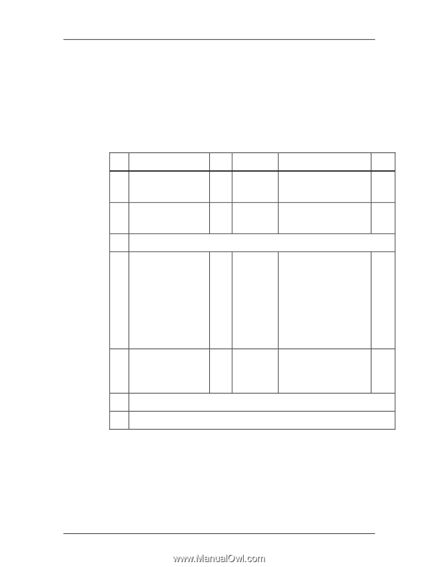
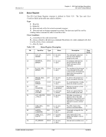
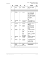
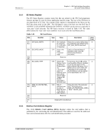
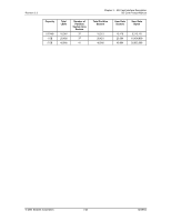
Revision 2.2 Chapter 3 - SD Card Interface Description SD Card Product Manual 3.5.5 3.5.6 SD Status Register The SD Status Register contains status bits that are related to the SD Card proprietary features and may be used for future application specific usage. The size of the SD Status is one data block of 512 bits. The content of this register is transmitted to the Host over the DAT bus along with 16 bits CRC. The SD Status is sent to the host over the DAT bus if ACMD13 is sent (CMD55 followed with CMD13). ACMD13 can be sent to a card only in 'tran_state' (card selected). The SD Status structure is listed in Table 3-30. The same abbreviations for 'type' and 'clear condition' were used as for the Card Status above. Table 3-30 SD Card Status Bits Identifier 511- DAT_BUS_WIDTH 510 509 SECURED_MODE 508496 495- SD_CARD_TYPE 480 479- SIZE_OF_PROTECTED_ 448 AREA 447312 3110 Type Value Description Clear Cond. S R 00=1 (default) Shows the currently defined data A 01=reserved bus width that was defined by the 10= 4-bit width SET_BUS_WIDTH command 11=reserved S R 0=not in the Card is in Secured Mode of A mode operation (refer to the SD 1=secured Security Specifications mode document). Reserved S R '00xxh'=SD In the future, the 8 LSBs will be A Memory Cards used to define different variations as defined in of an SD Card (each bit will Physical Spec. define different SD types). The 8 Ver. MSBs will be used to define SD 1.01('x'=don't Cards that do not comply with care).The the SD Memory Card as defined following cards in the Specification Ver. 1.01 are currently defined:'0000' =Regular SD RD/WR Card.'0001'= SD ROM Card S R Size of Shows the size of the protected A protected area area. The actual area = (in units of (SIZE_OF_PROTECTED_AREA) MULT*BLOCK * MULT * BLOCK_LEN. _LEN refer to CSD register). Reserved Reserved for manufacturer Relative Card Address Register The 16-bit Relative Card Address (RCA) Register carries the card address that is published by the card during the card identification. This address is used for the addressed host-card communication after the card identification procedure. © 2004 SanDisk Corporation 3-22 12/08/04
-
 1
1 -
2
-
3
-
4
-
5
-
6
-
7
-
8
-
9
-
10
-
11
-
12
-
13
-
14
-
15
-
16
-
17
-
18
-
19
-
20
-
21
-
22
-
23
-
24
-
25
-
26
-
27
-
28
-
29
-
30
-
31
-
32
-
33
-
34
-
35
-
36
-
 37
37 -
 38
38 -
 39
39 -
 40
40 -
 41
41 -
 42
42 -
 43
43 -
 44
44 -
 45
45 -
 46
46 -
 47
47 -
48
-
49
-
50
-
51
-
52
-
53
-
54
-
55
-
56
-
57
-
58
-
59
-
60
-
61
-
62
-
63
-
64
-
65
-
66
-
67
-
68
-
69
-
70
-
71
-
72
-
73
-
74
-
75
-
76
-
77
-
78
-
79
-
80
-
81
-
82
-
83
-
84
-
85
-
86
-
87
-
88
-
89
-
90
-
91
-
92
-
93
-
94
-
95
-
96
-
97
-
98
-
99
-
100
-
101
-
102
-
103
-
104
-
105
-
106
-
107
-
108
-
109
-
110
-
111
-
112
-
113
-
114
-
115
-
116
-
117
-
118
-
119
-
120
-
121
-
122
-
123
 |
 |