SanDisk SDSDH-1024 Product Manual - Page 55
Send Number of Written Blocks
 |
UPC - 710348911073
View all SanDisk SDSDH-1024 manuals
Add to My Manuals
Save this manual to your list of manuals |
Page 55 highlights
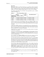
Revision 2.2 Chapter 4 - SD Card Protocol Description SanDisk SD Card Product Manual 4.4.5 4.4.6 whether the write process is still in progress). The host may deselect the card by issuing CMD7 (to select a different card) that will displace the card into the Disconnect State and release the DAT line without interrupting the write operation. When reselecting the card, it will reactivate busy indication by pulling DAT to low if programming is still in progress and the write buffer is unavailable. Actually, the host may perform simultaneous write operation to several cards with inter-leaving process. The interleaving process can be done by accessing each card separately while other cards are busy. This process can be done by proper CMD and DAT0-3 line manipulations (disconnection of busy cards). Send Number of Written Blocks Systems that use the PipeLine mechanism for data buffers management are, in some cases, unable to determine which block was the last to be well written to the flash if an error occurs in the middle of a Multiple Blocks Write operation. The card will respond to ACMD22 with the number of well-written blocks. Erase Identification of write blocks is accomplished with the ERASE_WR_BLK_START (CMD32), ERASE_WR_BLK_END (CMD33) commands. The host must adhere to the following command sequence: ERASE_WR_BLK_START, ERASE_WR_BLK_END and ERASE (CMD38). If an erase (CMD38) or address setting (CMD32, 33) command is received out of sequence, the card sets the ERASE_SEQ_ERROR bit in the Status Register and reset the entire sequence. If an out-of-sequence command (except SEND_STATUS) is received, the card will set the ERASE_RESET status bit in the Status Register, reset the erase sequence and execute the last command. If the erase range includes write-protected sectors, they will be left intact and only the unprotected sectors will be erased. The WP_ERASE_SKIP status bit in the Status Register will be set. The address field in the address setting commands is a write block address in byte units. The card ignores all LSBs below the WRITE_BLK_LEN (see CSD) size. As described above for block write, the card will indicate that an erase is in progress by holding DAT0 low. The actual erase time may be long, and the host may issue CMD7 to de-select the card or perform card disconnection, as described in the Block Write section, above. The card data after an erase operation is either "0" or "1", depending on the card vendor. The SCR register bit DATA_STAT_AFTER_ERASE (bit 55) defines whether it is "0" or "1". Write Protect Management Three write-protect methods are supported in the SD Card as follows. • Mechanical write-protect switch (host responsibility only) • Card internal write-protect (card's responsibility) • Password protection card-lock operation © 2004 SanDisk Corporation 4-11 12/08/04
-
 1
1 -
2
-
3
-
4
-
5
-
6
-
7
-
8
-
9
-
10
-
11
-
12
-
13
-
14
-
15
-
16
-
17
-
18
-
19
-
20
-
21
-
22
-
23
-
24
-
25
-
26
-
27
-
28
-
29
-
30
-
31
-
32
-
33
-
34
-
35
-
36
-
37
-
38
-
39
-
40
-
41
-
42
-
43
-
44
-
45
-
46
-
47
-
48
-
49
-
 50
50 -
 51
51 -
 52
52 -
 53
53 -
 54
54 -
 55
55 -
 56
56 -
 57
57 -
 58
58 -
 59
59 -
 60
60 -
61
-
62
-
63
-
64
-
65
-
66
-
67
-
68
-
69
-
70
-
71
-
72
-
73
-
74
-
75
-
76
-
77
-
78
-
79
-
80
-
81
-
82
-
83
-
84
-
85
-
86
-
87
-
88
-
89
-
90
-
91
-
92
-
93
-
94
-
95
-
96
-
97
-
98
-
99
-
100
-
101
-
102
-
103
-
104
-
105
-
106
-
107
-
108
-
109
-
110
-
111
-
112
-
113
-
114
-
115
-
116
-
117
-
118
-
119
-
120
-
121
-
122
-
123
 |
 |
